Welcome to X3DOM
Welcome to X3DOM’s documentation. This documentation is divided into different parts: Guide, Reference and Notes. We recommend that you read the Getting started section of the Guide first. Besides the getting started there is also a more detailed First steps with X3DOM tutorial that shows how to create complete (albeit small) application. If you’d rather dive into the internals of X3DOM, check out the API documentation.
Guide
This part of the documentation, which is mostly prose, begins with some basic information about X3DOM, then focuses on step-by-step instructions for building applications with X3DOM.
Getting started
Using X3DOM
The recommended way of using X3DOM during the development of your application is linking the online version within your HTML document. You can use the following boiler-plate to kick-start development:
<!doctype html>
<html>
<head>
  <meta encoding="utf-8">
  <script src="http://www.x3dom.org/download/dev/x3dom.js"></script>
  <link rel="stylesheet" href="http://www.x3dom.org/download/dev/x3dom.css">
</head>
<body>
  <x3d> ...</x3d>
</body>
</html>
X3DOM should be usable in all modern browser and depends on no external libraries.
Please be aware that hot-linking the X3DOM library as outlined above will give you the cutting-edge build of the library with all pros and cons. You will recieve the latestest fixes and features, but also a potentially unstable or temporarliy broken version. We try to maintain a unbroken dev build, but that can’t be guaranteed all the time.
Once you finished developing your application, you should download the necessary snapshot build and deploy the files with your application on your server or a CDN. All you need in order to make it work are the following files:
| x3dom.js | The minified X3DOM library in a given version. |
| x3dom.css | Stylesheets for X3DOM, you need to include this file in your webpage in order for X3DOM to display. However you can also take it as template to adapt your own stylesheet. |
| x3dom.swf | The Flash 11 integration, for browsers not supporting native X3DOM or WebGL. |
You can download the files from the X3DOM server and put them on your harddisk or your webserver. The released versions reside in subdirectories with version numbers, for example version 1.4 is available at 1.4/. For the current development build you can use the shortcut dev/ it will always point to the latest released version.
Releases, dev builds and library management
Since X3DOM is a research project our official release cycle is fairly long. In order to keep your application up-to date with any browser related incompatibilities, you need to manage a local copy of the X3DOM development build along with your application. In other words: the released versions are not maintained. Therefore the following release/library management on your side might be one sensible approach:
- Use the dev build during development of your application
- Use the released version if you deploy in a controlled environment (Browser and OS versions)
- Freeze the dev build (or use a release in a controlled environment) and deploy that freezed version anlongside your application on your server or CDN
- If browser issues occur, use the latest X3DOM dev build and test your application thourougly.
- Monitor your environment regulary and perform your own tests with all browser versions and OS combinations your application is targed for as soon as a X3DOM or browser changes occur
It should be stressed that X3DOM as well as browser development is a moving target. It is only sensible to adjust your development and library management processes to this environment.
Development builds
If you want to work with the latest development build of X3DOM (which in fact is recommended), then download the latest builds from the X3DOM server here.
The development build is automatically created every night and will contain many fixes and features not available to the released versions. We try to keep the development build at a working stage and not break compatibility with released versions. However, a working dev build can not be guaranteed all the time.
Build your own
Note: If you wish to use a rather recent version of X3DOM and do not want to tinker with the build process, just use the development build. If you like to work on X3DOM itself, use the instructions set forth in this chapter.
All source code to X3DOM is kept under the Git revision control and you can browse the repository online. There is a download link available for any file or directory, if you only nee a portion of the X3DOM code.
If you have access to Git, you can get a copy of the repository here:
git clone https://github.com/x3dom/x3dom.git
You can also check out a specific release from GitHub:
git clone https://github.com/x3dom/x3dom.git
git checkout <version>
e.g. git checkout 1.3.0
If you want to build your own copy of X3DOM from the Git repository, you need to build it from the sources.
Build requirements
X3DOM currently requires the following components to be installed on your computer:
- Python: The Python programming language is available for all major platforms. The recommended version is 2.7, but 2.6 works fine too.
- Sphinx: A documentation tool, you will need this in order to build the documentation. Sphinx is a Python package and can be installed by running easy_install sphinx.
- argparse: For Python 2.6 or earlier.
Once you have all prerequisites installed, you can build X3DOM:
python manage.py --build
The resulting build will be written to the dist/ directory.
Fore more detailed information on working with the source, please see the developer wiki.
Tutorial
You want to develop an application with X3DOM? Here you have the chance to learn that by example. In these tutorials we will create simple applications of different kinds, but they still feature everything you need to get started.
Basic operation
First steps with X3DOM
This tutorial is intended to be a quick start for people who have no experience with 3D graphics so far but want to try out X3DOM. Those who want to learn more about it, should have a look at the book X3D: Extensible 3D Graphics for Web Authors about X3D, on which X3DOM is based, by Don Brutzman and Leonard Daly.
Authoring X3DOM content is very similar to authoring HTML. So just open an editor and start with the usual stuff as shown next. Please note the <link> tag, which includes the X3DOM stylesheet for having everything nicely formatted, and the <script> tag, which includes all JavaScript functions that are necessary to run your 3D scene:
<html>
  <head>
    <title>My first X3DOM page</title>
    <link rel="stylesheet" type="text/css"
          href="http://www.x3dom.org/download/x3dom.css">
    </link>
    <script type="text/javascript"
            src="http://www.x3dom.org/download/x3dom.js">
    </script>
  </head>
  <body>
    <h1>My X3DOM world</h1>
    <p>
      This is my first html page with some 3d objects.
    </p>
  </body>
</html>
Save your file and open it in an WebGL capable browser. As you can see, there is only some text. What’s missing are the X3DOM-specific tags for specifying the 3D objects.
Hence, we’ll now insert a red box into our page by inserting the following code after the closing <p> tag. Similar to a <p> or <div> element, the <x3d> element defines a rectangular region that contains all its children elements (in this case the red box).
<x3d width="500px" height="400px">
  <scene>
    <shape>
      <appearance>
        <material diffuseColor='red'></material>
      </appearance>
      <box></box>
    </shape>
  </scene>
</x3d>
You might wonder, why the <box> tag isn’t enough and what the other tags are good for. <scene> simply says, that you are going to define a 3D scene. And a <shape> defines the geometry (here a <box>) as well as the <appearance> of an object. In our example, the whole appearance only consists of a red <material>. If you want to learn more about these elements (or nodes as they are called in X3D), just follow this link and click on the node you are interested in.
Because simply looking at one side of the box is bit boring, you can navigate within your scene with the help of the mouse. If you move the mouse with pressed left mouse button inside the area surrounded by a black border, you’ll rotate the point of view. With the middle mouse button you can pan around and with the right button you can zoom in and out. For more information see: Camera Navigation.
Ok, now you can move around, but admittedly this scene still is sort of boring. Thus, we’ll add another object, a blue <sphere>, into our little scene. As is shown next, the <shape> is now surrounded by another element, the <transform> tag. This is necessary, because otherwise both objects would appear at the same position, namely the virtual origin of the 3D scene.
Thereto, the ‘translation’ attribute of the first <transform> element moves the box two units to the left, and the ‘translation’ attribute of the second <transform> element moves the sphere two units to the right. As can be seen in the example below, the value of the ‘translation’ attribute consists of three numbers. The first denotes the local x-axis (movement to the left/ right), the second defines the movement along the local y-axis (up/ down), and the third defines the movement along the local z-axis (back/ front).
<x3d width="500px" height="400px">
  <scene>
    <transform translation="-2 0 0">
      <shape>
        <appearance>
          <material diffuseColor='red'></material>
        </appearance>
        <box></box>
      </shape>
    </transform>
    <transform translation="2 0 0">
      <shape>
        <appearance>
          <material diffuseColor='blue'></material>
        </appearance>
        <sphere></sphere>
      </shape>
    </transform>
  </scene>
</x3d>
Now you know the basics of X3DOM. As you might have expected, there are certainly more nodes or elements you can try out like the <cone> or the <cylinder>. Also, there are other material properties like ‘specularColor’ and ‘transparency’. By applying an <imageTexture> to your object, you can achieve fancy effects like a teapot that looks like earth as demonstrated in this example. When you have a look at the example’s source code, you’ll find a new tag called <indexedFaceSet>, which can be used for creating arbitrary kinds of geometry.
The example discussed here is also available online. Moreover, there are already lots of other X3DOM examples. Just try them out, and even more important, have a look at the source code to learn what’s going on.
Please note, that there are slight differences between XHTML and HTML encoding: e.g. the latter does not yet work with self-closing tags but requires that tags are always closed in the form </tagName>.
If you ever have problems, please first check the Troubleshooting section of this guide, much helpful information is collected there.
Styling with CSS
This tutorial guides you through the process of using CSS with X3DOM. In order to demonstrate the functionality, we are going to create a HTML document with a X3DOM scene. That scene is then amended with a button that allows to resize the scene by setting CSS attributes using JavaScript.
Important: you should always include the X3DOM default stylesheet x3dom.css, since it initializes some important settings necessary due to the fact that X3DOM’s new 3D elements are unknown to the Browser and so are their styles. For example, if the <x3d> element is not floating (e.g. using the float:left property), the relative mouse positions cannot be calculated correctly and picking does not work!
Basic scene document
We are going to use the box example scene established in the First steps with X3DOM tutorial:
<!DOCTYPE html>
<html>
<head>
<meta charset="utf-8">
<title>CSS Integration Test</title>
<link rel="stylesheet" href="http://www.x3dom.org/download/x3dom.css">
<script src="http://www.x3dom.org/download/x3dom.js"></script>
</head>
<body>
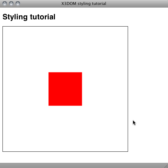
<h1>Styling tutorial</h1>
<x3d width="400px" height="300px">
<scene>
<shape>
<appearance>
<material diffuseColor='red'></material>
</appearance>
<box></box>
</shape>
</scene>
</x3d>
</body>
</html>
Rendering this document in a WebGL compatible browser, results in a look similar to this:
Basic styling
In the initial example above, we created the scene using the <x3d> tag initializing it with `width` and `height` attributes. In order to take advantage of CSS, we can use a CSS rule to set height and width in the visual layer.
The following CSS rules, added to the <head> of the HTML document element will resize the scene to 50% height and with of the parent element - in this case the body element. In order to make this work with IDs, we need to add the `id` attribute to the <x3d> element:
<head>
  <style>
    #the_element {
      width: 50%;
      height: 50%;
    }
  </style>
</head>
...
<x3d id="the_element">
...
We need to remove the width and height attributes as well because they take precedence over the CSS rules. In order to change the background of the WebGL viewport we add the CSS background rule. To make this work, the scene must be transparent (default). If you change the background in the X3D definition, it will not be visible because it is disguised by the X3D background.
#the_element {
    width: 50%;
    height: 50%;
    background:#000 url(http://www.x3dom.org/x3dom/example/texture/solarSystem/starsbg.png);
 }
The result looks something like this:
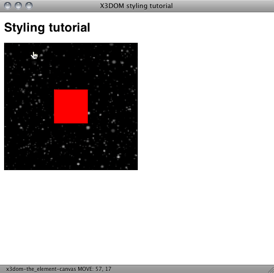
Note that the dimensions are relative now and adapted when resizing the browser window.
Adding interaction
The dynamic resizing showed in the last chapter is great for automatically adapting to browser resize and for positioning elements in your layout. In order to add more elaborate interaction with the scene, we can use JavaScript. For example, to change the dimensions of the X3D element so we can resize it to “fullscreen” like the ubiquitous video player.
In order to achieve this we are going to add a button to our example that allows to switch our X3D element to fullscreen – or more precisely to 100% of the parent HTML element.
First step is adding a piece of markup that we can use for styling as a button. Fortunately there already is a HTML element that is meant for exactly this purpose: <button>. And since we move in a HTML5 context, we put the button element within the <x3d> element:
<x3d id="the_element">
    <button id="toggler">Zoom</button>
    <scene>
    ...
</x3d>
Semantically we are fine, but now we need to style the button so it floats over the scene. The following style rules will accomplish this. Please note the position: relative property we are setting on the x3d element. We need this to allow absolute positioning of the button within the x3d element. Otherwise it would position absolute to the page. Additionally we need to remove the default 1 pixels border added by the X3DOM default stylesheet.
#the_element {
    ...
    border: none;  // remove the default 1px border
    position: relative;
 }

#toggler {
    position: absolute;
    float: left;
    z-index: 1;
    top: 0px;
    left: 0px;
    width: 10em;
    height: 2em;
    border: none;
    background-color: #202021;
    color: #ccc;
}
Looking at our example in a browser reveals that there is a “Zoom” button floating over the x3d element in the top left corner.
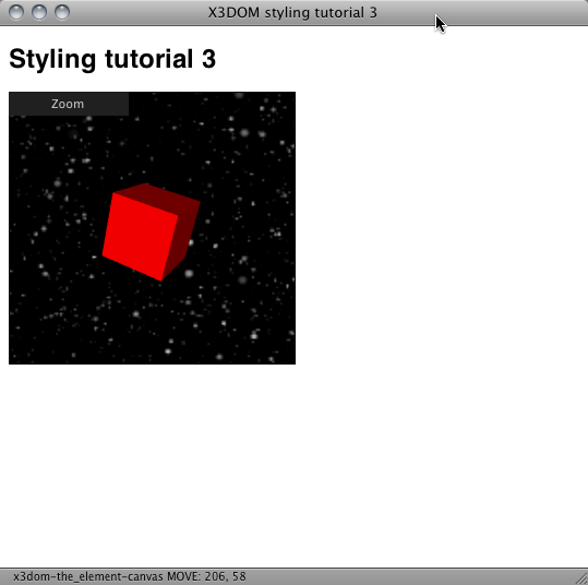
### A button alone isn’t interaction
Nice. But a button alone is quite useless, we need to be able to do something with it. But first things first. In order to give the user some feedback what is going on, we add a hover effect by simply changing the background color. This is basic usability and a simple style rule will do the job:
#toggler:hover {
    background-color:blue;
}
Next we add some JavasScript to the mix, because we want to actually change something when the user clicks on the button: Fullscreen. First we think of a method name to use, like toggle() and attach it to the onclick event of our button:
<button id="toggler" onclick="toggle(this);return false;">Zoom</button>
Note to the purists: Yes, there are several, more elegant ways of achieving this. For the sake of clarity of this tutorial, we are using the onclick attribute of the button element. In practice you probably want to use a DOM library like jQuery et al.
Next, we need to implement the toggle function. Within a script element. After the inclusion of x3dom.js we add the following code:
var zoomed = false;

function toggle(button) {

        var new_size;
        var x3d_element;

        x3d_element = document.getElementById('the_element');

        title = document.getElementById('title')
    body  = document.getElementById('body')

        if (zoomed) {
                new_size = "50%";
                button.innerHTML = "Zoom";
                title.style.display = "block"
                body.style.padding = '10px'
        } else {
                new_size = "100%";
                button.innerHTML = "Unzoom";
                title.style.display = "none"
                body.style.padding = '0'
        }

        zoomed = !zoomed;

        x3d_element.style.width = new_size;
        x3d_element.style.height = new_size;
}
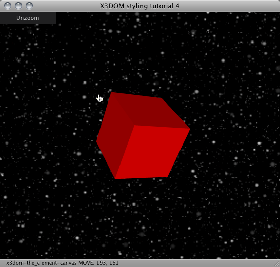
This code implements a simple toggle function. The boolean variable zoomed tracks the state of the resize. Depending wether the x3d element is sized to 100% or not, the new size is set and applied to the x3d element (x3d_element). Since we use a square viewport width and height have the same values. Additionally, the text of the button is changed to show the action performed when the user is clicking it.
The rest of the styling affects the surrounding elements like the title and the body. In order to achieve the fullscreen effect we obviously hide the h1 title and remove the default padding of the body element. Likewise when zooming back, the values are restored.
The last bit in the puzzle is another style rule which resets margin and padding of the body element. Add this rule in front of all others:
<style>
    body {
        margin:0;
        padding:10px;
    }
    ...
</style>
Finally the fully zoomed result looks like this:
You will also find another example which also styles other properties here.
Images, sound and movie formats
This tutorial shows what type of image, sound and movie formats can be used in X3DOM and what are the features and restrictions.
Images
You can use PNG, JPEG or GIF to encode your static Texture data. JPG has a low memory profile but has a lossy compression and it does not support alpha channels. PNG compression is lossless and can handle alpha. GIF is also lossless and has alpha.
General: If you do not need an alpha channel and the content does not have hard edges (e.g. Text) use JPG. Otherwise use PNG. You should really not use GIF anymore. PNG is more flexible for future content (e.g. 16-bit channels).
<ImageTexture url=’foo.jpg’ />
Sound
You can use WAV, MP3 and OGG for sound sources. All UA should support WAV. If you would like to use compressed formats (e.g. MP3 or OGG) provide alternative encodings in your AudioClip node.
<AudioClip url=’”foo.wav”,”foo.ogg”‘ />
Movies
There is right now no single movie file supported by all user agents. Use the X3DOM formats exmaple to check your browser.
The best solution right now is to encode your content as MP4 and OGV movie and provide alternative sources in your MovieTexture node.
<MovieTexture url=’”foo.mp4″,”foo.ogv”‘ />
Shadows
This tutorial shows how to add shadows to your scene and how specific shadow settings can be used to influence shadow quality and performance.
Turning on shadows
To be able to use shadows, you first need a light source. What kind of light source does not matter – shadows can be used with directional lights and spot lights as well as point lights. Shadow rendering is turned on, when the shadowIntensity property of a light node is set to a value greater than zero (see code snippet below). The higher the setting, the darker the shadows will be. However, be advised that shadow computations are quite expensive and can have noticable impact on the performance of your application.
<directionalLight direction='0 0 -1' intensity='1.0' shadowIntensity='0.7'>
</directionalLight>
Basic shadow settings
One of the most important settings – both regarding the visual quality of the shadows and the performance – is the shadowMapSize setting. A shadow map is a texture which captures the scene from a light’s point of view and is the basis for all shadow computations in X3DOM. The size of the shadow map determines the resolution at which shadows are computed. The standard setting of 1024 should achieve good results in most cases, but depending on the situation you might want to change it anyway. In general, a higher shadow map resolution leads to more detailed shadows, but also to a significant drop in performance.
Another option which has significant impact on the quality of the shadows is shadow map filtering. Filtering makes the edges of the shadows seem smoother. It can be controlled with the shadowFilterSize attribute. A higher filter size increases the amount of blurring that is applied to a shadow map. However, the effectivenes of this technique does not only depend on the filter size, but also on the resolution of the shadow map. A high-resolution shadow map requires a higher filter size setting for filtering to be effective.
Cascading
Another technique to improve shadow quality which is especially helpful in big scenes is called cascading: the visible area is parted along the z-axis and for each of the created divisions (cascades) shadows are computed independently. The number of cascades to be used can be set with the shadowCascades option. Cascading can be used with directional lights and spot lights, but not with point lights. Be advised that this technique is only effective, if the light covers a relatively big area. Consequently, the main application scenario lies in the usage with a directional light.
Advanced shadow settings
With the right combination of shadowMapSize, shadowFilterSize and shadowCascades a satisfyable shadow quality should be achievable in most cases. However, there are situations in which further adjustments might be needed, which is why an additional set of shadow options was introduced into X3DOM. The first one – shadowOffset – is used to hide artifacts which may occur in specific scenarios. One of these situations that is escpecially susceptible to inaccuracies is a scene in which the light direction is nearly parallel to an object’s surface. By increasing the shadowOffset the shadow artifacts become less pronounced. However, not only artifacts are affected by this setting, but to some degree the correctly drawn shadows are, too. A high shadow offset can result in light to leak onto objects which should be in shadow. For this reason the default offset value is zero.
Further options to influence shadow computations are given by the light node’s zNear and zFar properties. These settings determine the placement of the near and far planes of the light projection, i.e. the bounds of the area in which shadow casters are captured. If no such setting is given, the near and far planes are placed automatically. An example scenario where a manual setting of one of these planes might be helpful would be a scene where an object is placed very closely to the light source. If you don’t want that object to cast a shadow, the zNear setting can be set to a value which places the near plane behind that object and thereby excludes it from the shadow computations. (Please note: if the shadows disappear when a shadow caster leaves the visible view area, then try setting the Environment bindable node’s frustumCulling field to false.)
The last two settings – shadowSplitFactor and shadowSplitOffset – are additional parameters for cascading. As mentioned before, when using shadow cascades the visible area is split along the z-axis. The shadowSplitFactor setting determines, how these splits are placed. A setting of zero gives an equidistant placement, a setting of one a logarithmic placement. In most cases a logarithmic placement should achieve better results, since it allocates more resolution to the close range where it is needed the most. However, the equidistant split scheme can still be useful in some scenarios, as the transitions between different cascades are less apparent. The shadowSplitOffset option was introduced, because in some cases the cascades close to the near plane can get quite small. While this is good for shadow quality in that specific cascade, the transition to the next cascade will become all the more apparent. By using the shadowSplitOffset property, the split positions are moved away from the camera while the computation scheme that is defined by shadowSplitFactor is still respected.
Content creation
Generic 3D data conversion
How to get your 3D asset in your application is one of the essential questions that every 3D runtime environment has to answer.
X3DOM uses X3D data embedded in (X)HTML pages and optional X3D-XML files referenced by the embedded part. The X3D-XML files can reference further X3D-XML files and therefore build a hierarchy of asset containers.
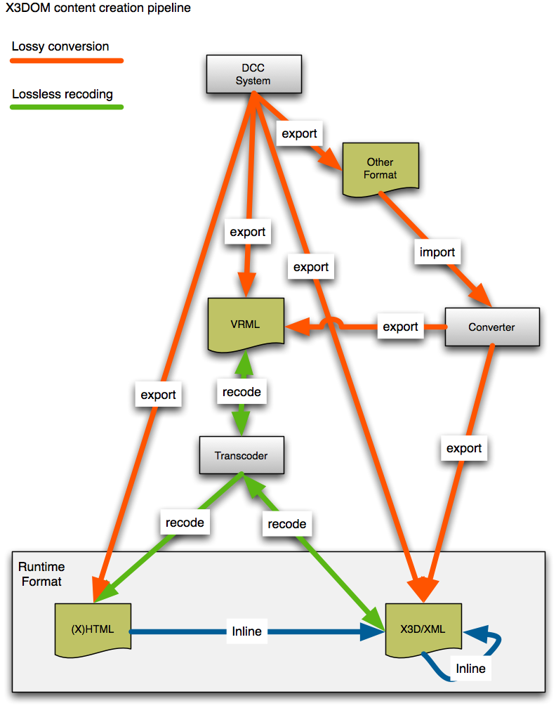
This tutorial shows how to get your data into the X(HTML) page and how to convert it to X3D-XML so it could be externally referenced.
DCC export
Usually people use some form of Digital Content Creation (DCC) tool to build the 3D models. This can be a modeling system like Maya or 3D Studio Max, and also a CAD-System or simulation package.
They all usually allow exporting the internal representation to some form of 3D data file. Most support X3D or VRML, some even both (e.g. blender) plus other formats. For X3DOM you should look for a X3D exporter. VRML is your second best choice. X3D is a VRML derivate and superset.
Converter
If your DCC-tool does not support X3D or VRML you are forced to utilize another tool which will introduce a extra level of conversion. Depending on your format there are usually different converters. Refer to X3D/web3d.org data conversion for more information.
However, you should really try to avoid this step and export directly to X3D or VRML.
Transcoding
If you have an X3D-XML or VRML file you can easily recode your data without any data loss. There are different options but the easiest right now is properly the Avalon-Optimizer (aopt) from the InstantReality packages. You can use it online or on your local machine to recode your data.
Offline Transcoding
Download and install the InstantPlayer system. The package includes a command line tool called aopt(.exe) which we will use for conversion. Setup your shell-environment to find and include the binary. The usually paths are:
- Windows: C:\Program Files\Instant Player\bin\aopt.exe
- Mac: /Applications/Instant Player.app/Contents/MacOS/aopt
- Linux: /opt/instantReality/bin/aopt
Then run aopt -h command to get a full list of options and usage instructions. For this tutorial the most important are:
aopt -i foo.wrl -x foo.x3d      # Convert VRML to X3D-XML
aopt -i foo.x3d -N foo.html     # Convert VRML or X3D-XML to HTML
aopt -i foo.x3d -M foo.xhtml    # Convert VMRL or X3D-XML to XHTML
aopt -i foo.x3d -u -N foo.html  # Optimization and build DEF/USE reuses
Building the File Hierarchy
A hierarchy of files can be built up with Inline nodes. The advantage here is that bigger objects/ meshes do not need to be directly part of a page’s source code, but can be loaded in parallel in the background.
Important: If you use <Inline url=”foo.x3d” /> nodes in your content, you need a real server to run your application. This will not work locally from your disc.
Analyzing and optimizing your model for the 3D Web
The InstantReality platform provides its users tools to help them better understand and optimize their (possibly large) 3D data sets. One such tool is aopt that (among other things) can help you in various ways to optimize 3D models with a special focus on scene-graph data.
While on Windows and Linux the aopt tool is simply located in Instant Reality’s bin folder, on Mac it is sort of hidden here:
/Applications/Instant Player.app/Contents/MacOS/aopt
aopt
aopt is a powerful command line tool that comes bundled with InstantReality. If you have InstantReality installed, opening your command line and entering “aopt” will provide you with a list of all available command line arguments and some examples of its usage. A very basic procedure for example would be to convert a file that InstantReality can open (e.g. in obj, ply or wrl format) into an X3D file:
aopt –i [input.foo] -x [output].x3d
(Note: leave out “[” and “]” for the actual command line with your files.)
Or to HTML:
aopt –i [input.foo] -N [output].html
For a general introduction to data conversion with aopt check here. Generelly, you get some more advice calling aopt -h and aopt -H.
Analyzing your 3D model
You can get some basic statistics for your file using the “-p” parameter:
aopt -i [input.foo] -p
This will give you some basic information like the number of nodes and the numbers of various types of nodes. For example, a scene that is static but heavy on the number of nodes might be suited for automatic restructuring (see below).
ImageGeometry & BinaryGeometry nodes
If you want to retain the basic structure of your scene-graphs (i.e. not change any of the nodes, only their contents) you can convert geometry nodes to special ImageGeometry or BinaryGeometry nodes that will apply advanced compression techniques. This will create additional files that are referenced from <output>.x3d, so you should first create a folder, e.g.:
mkdir imggeo
aopt -i [input.foo] -g imggeo/:s -x [output].x3d
Note: currently it is import that “imggeo” (or any folder you choose) does exist. Please also note that the “/” is NOT optional, it needs to be added at the end of the path.
The ”:is” part is a sub-parameter. “i” is for “index” and “s” for “strip”, so this example will generate and store indexed trianglestrip geometry. For ImageGeometry nodes these are the only options available and it is recommended to either use s or is.
As an alternative you can convert to BinaryGeometry instead of ImageGeometry nodes:
mkdir bingeo
aopt -i [input.foo] -G "bingeo/:is" -x [output].x3d
Or convert to HTML using 16 bit interleaved attribute buffers:
mkdir bingeo
aopt -i [input.foo] -G "bingeo/:saI" -N [output].html
This conversion leads to geometry nodes that look like the one shown next:
<binaryGeometry vertexCount='1153083' primType='"TRIANGLES"'
    position='19.811892 -57.892578 -1.699294'
    size='92.804482 159.783081 26.479685'
    coord='binGeo/BG0_interleaveBinary.bin#0+24' coordType='Int16'
    normal='binGeo/BG0_interleaveBinary.bin#8+24' normalType='Int16'
    color='binGeo/BG0_interleaveBinary.bin#16+24' colorType='Int16'>
</binaryGeometry>
For BinaryGeometry the available parameters are shown next.
- i: index
- s: trianglestrip
- a: autoIndex (only index data with less than 16 bit indices)
- c: compact (use 16 bit representation for vertex attributes)
- p: normal in spherical coordinates
- I: interleaved (use 16 bit interleaved vertex data)
The most compact option for BinaryGeometry is using “sacp”. In the following little example, first creaseAngle is set to a value greater Pi to avoid per face normals, then a suitable viewpoint is generated with the -V option, and finally binary meshes are created.
mkdir binGeo
aopt -i [input.foo] -f PrimitiveSet:creaseAngle:4 -V -G "binGeo/:sacp" -N [output].html
Mesh restructuring
If you are willing to completely restructure the scene-graph to increase performance, you can use this function:
aopt -i [input.foo] -F "Scene:opt(1),maxtris(20000)" -x [output].x3d
This will try to automatically optimize your scene, for example it might try to merge (flatten) your whole scene, generate one or more texture atlases on the way or split all geometry nodes so they can be indexed with 16 bits.
Instead of Scene you can also have specific node names or node type names for a more targeted approach. The sub-parameters in this example configure aopt to create a single-index geometry with up to 20,000 triangles per geometry node.
It’s not necessary to set any sub-parameters here. Next, an example is shown how to also accomplish mesh optimization (here of a ply model) by calling aopt three times, for cleanup, mesh patching (for coping with the 16 bit indices limit), and final binary geometry creation.
aopt -i model.ply -u -b model-clean.x3db
aopt -i model-clean.x3db -F Scene -b model-opt.x3db
aopt -i model-opt.x3db -G binGeo/:saI -N model.html
Currently available sub-parameters for the “-F” option are:
- int opt: 0:none 1:createSingleIndex 2:createSharedIndex 3:optimizePrimitives
- int maxtris: Maximum number of triangles per geometry node
- int vertexcolor: Store material color in vertex color, if the amount of triangles in the geometry is under the threshold
- int texcoords: Ignore geometry with texture coordinates greater than that value
- int optimizeTC: Try to lower texture coordinates to this value (generates more triangles)
- bool storeondisk: Geometries are stored on disk (lower Memory consumption during process)
- bool toworld: The vertex positions are transformed to world coordinates
- bool idmap: Should an ID map be created?
- bool flat: Scene is stored in a flat graph (true), or in a hierarchy (false)
- bool cacheopt: Merges all geometry nodes with same material and rebuild it to chunks of 65,535 (= 2^16 - 1) vertices
- bool calcnormals: false to keep normals, true to recalc them after building new geometries
- int maxIndexSize: Maximum index size for rebuild by index/texture
- int maxTextureSize: Maximum texture size for rebuild by texture size
- float centerBB: Output will be transformed to a centered BBox with given size
Example:
aopt -i [input.foo] -F "Scene:maxtris(5000),flat(true),calcnormals(false),centerBB(50)" -x [output].x3d
Note: Depending on the operation the internal tree optimization method chooses, not all parameters are used! Boolean values can be both, 0/1 and false/true.
Blender export
Converting Blender scenes into X3DOM webpages is pretty simple: Blender already supports direct X3D export even so there are some issues (Don Brutzman wrote about). Blender Version 2.4 seems to export some more nodes (e.g. lights), but in general it works. We will explore this more in the future, but an exported X3D file (such as the little horse shown below) may afterwards be easily be integrated into an HTML webpage using X3DOM.
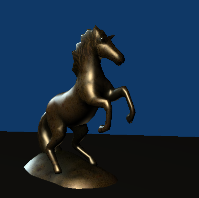
Horse model courtesy of http://etyekfilm.hu/
Just finish your model in Blender and export to x3d file format (see next image).
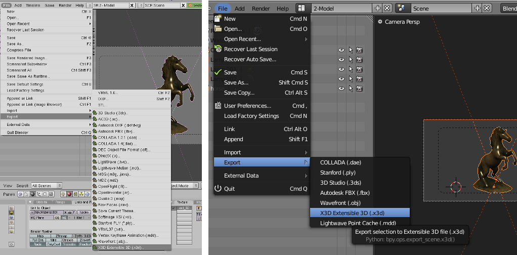
Export in Blender 2.4 (left) and 2.5 (right)
There are two ways to get your X3D data into the HTML page, and both include no coding at all:
Two-file solution, link the X3D-file
Just use a very simple X3D scene in your HTML file, which, more or less, only includes an <inline> node. This nodes references and asynchronously downloads the X3D file. Therefore you need a real web server (e.g. Apache) running while using <inline> nodes in X3DOM.
The result: http://x3dom.org/x3dom/example/blenderExport/horse-inline.html
One-file solution, embed the X3D data inside of the HTML page
You can embed the X3D file by hand in a (X)HTML page, but this may include some hand-tweaking. Better use the aopt-converter described in Generic 3D data conversion. This can be done offline with a single command:
aopt -i horse.x3d -N horse.html
You also may use the converter online. Just open horse.x3d with your favorite text editor and paste it into the source text field. Choose XML encoding (X3D) as input type and HTML5 encoded webpage as output type and press the Convert encoding button.
The result: http://x3dom.org/x3dom/example/blenderExport/horse.html
The main difference between the two versions is the handling of Viewpoint nodes (as cameras are called in X3D). If you use the two-file solution, you get a spec-compliant standard camera, while the viewpoints in the included data are not available at the beginning. In the one-file solution you already have the Viewpoint nodes from Blender at the start time. Just copy one of the viewpoints into the main HTML page to correct this behavior if you want.
Here is a zip archive (272kb) with all files used in this tutorial including blender model, texture, and x3d model.
3ds Max Export
If you are using Autodesk 3ds Max for modeling (available only for Microsoft Windows), you can install our exporter plug-in InstantExport. If you do not yet have installed 3ds Max, there is also a 30-day trial version of the modeling software available. Nightly beta builds of InstantExport are available for download here.
InstantExport is the InstantReality X3D exporter for 3ds Max and not only exports XML-based X3D as well as VRML, its classic encoding, but it can also now directly export to HTML/XHTML. But please note that – as the exporter plug-in is still under development – there are still lots of features in Max, which yet cannot be properly exported. So, if you find a bug, please report it in the InstantReality forum.
Installation
After having downloaded the exporter, unzip the zip file and choose the correct version for your system and Max version. After that, (assumed you are using the standard installation path and 3ds Max 2008) copy the file InstantExport.dle (the Max version of a DLL) into C:\Program Files\Autodesk\3ds Max 2008\plugins.
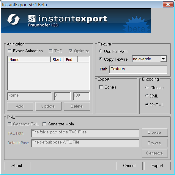
Export
Then start 3ds Max, load the 3d model you want to export, choose Export in the File menu, type in a file name, e.g. test.xhtml, and select the file type – in this case InstantExport (.WRL,*.XHTML,*.X3D)* After that, the exporter GUI pops up. Here, under Encoding choose XHTML, as shown in the screenshot below. Finally, press the Export button. For more information, the zip file also includes a help file for the exporter.
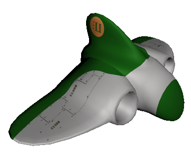
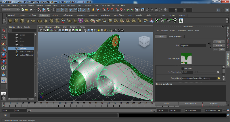
Maya export
If you are working with Autodesk Maya for modeling, shading and animating your 3d scenes, use this tutorial to create an interactive X3DOM website out of your model. This tutorial is tested with Autodesk Maya 2011. Nevertheless, the procedure should work even for older Maya versions.
The basic idea is to export your scene to VRML and convert this to an X3DOM/HTMLsite using InstantReality’s aopt binary (see Generic 3D data conversion).
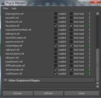
Step 2
Open ‘Window | Settings/Preferences | Plug-in manager’ and check the ‘loaded’ or ‘Auto load’ option vrml2Export.
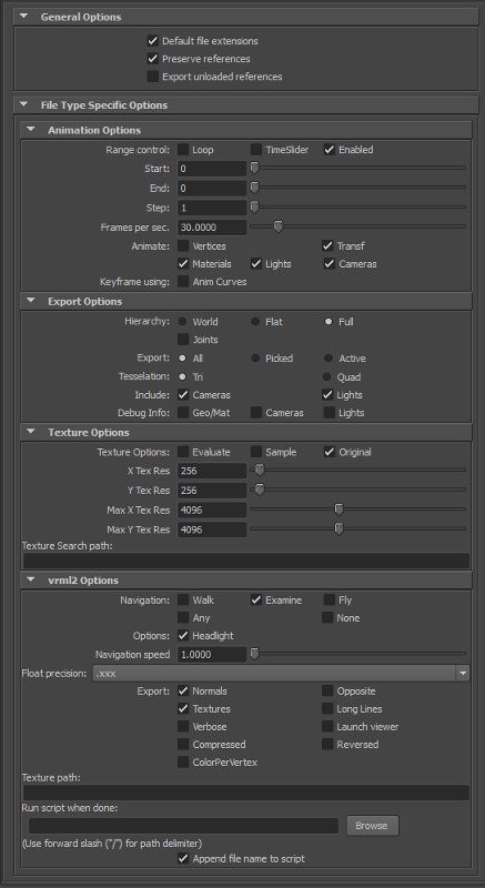
Step 3
Open the Export dialog under ‘File | Export All..’, Enter a filename (.wrl suffix) and switch to filetype ‘vrml2′. Don’t forget to check the following export options:
Hierarchy: FullTexture Options: OriginalExport: Normals and Textures
Click the “Export All” button. This will create a vrml2 file in your scenes folder.
Step 4
Open a terminal or command prompt, change to the folder containing your vrml2 model and your textures and run aopt (part of InstantReality, see Generic 3D data conversion for details) by typing the following command (assuming to be spaceship.wrl the name of your model):
| aopt -i spaceship.wrl -d Switch -f ImageTexture:repeatS:false
|      -f ImageTexture:repeatT:false -u -N spaceship.html
Note: aopt is automatically coming with your InstantReality player installation. You will find the executable within the bin folder of the Player. If you don’t have Instant Reality installed yet, download and install from www.instantreality.org.
Step 5
Maya is using absolute path names. Therefore, open your html file with a standard text editor (vi, emacs, notepad++, etc.) and remove all paths from ImageTexture. For example, replace:
url=’”c:\users\me\maya\project\sourceimages\spaceship_color.png”‘
with:
url=’”spaceship_color.png”‘
Step 6
Copy HTML and textures into your web folder and open the website with your X3DOM capable browser.
If you want to try out this tutorial: Here is a zip archive (208 kb) containing all relevant files including Maya model and texture.
You want to see the result live in your browser? Here is the final webpage
World of Warcraft Models to X3DOM
WARNING: World of Warcraft Models are Blizzard property. You can not use them on your site without permission from Blizzard.
The WOWModelViewer project is an open source application to create machinima with characters and models form the World of Warcraft MMORPG. One of its features is the ability to export models into various formats, two of them being X3D and X3DOM. The X3DOM option directly outputs an XHTML file with the appropriate header code. In its current released version 7.0.1 r462, only static models can be exported, but an option to export animations as well is already available in the code.
To export a model you’ll need a full World of Warcraft installation (for instance a 10 day trial version) and the WOWModelViewer. Open the application, select a model on the right hand side and click on File->Export model->X3D in XHTML.
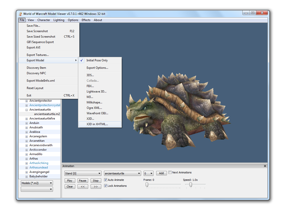
The exported files can be viewed in a X3DOM capable browser.
Some video results can be watched here:
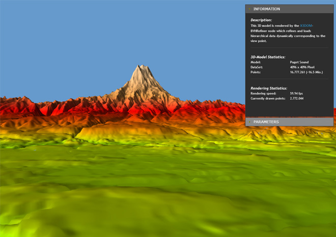
The BVHRefiner component - Refining and Loading hierarchical data dynamically
The BVHRefiner is a component that refines and loads hierarchical data dynamically during runtime. Two different dataset structures can be used (WMTS, TREE) that are described later.
3D-Example of Puget Sound rendered with a WMTS conform dataset
<BVHRefiner maxDepth='5'
            minDepth='2'
            interactionDepth='4'
            subdivision='64 64'
            size='4096 4096'
            factor='10'
            maxElevation='410'
            elevationUrl="Puget Sound WMTS/elevation"
            textureUrl="Puget Sound WMTS/satellite"
            normalUrl="Puget Sound WMTS/normal"
            elevationFormat='png'
            textureFormat='png'
            normalFormat='png'
            mode="3d"
            submode="wmts">
</BVHRefiner>
Parameter descriptions
The following table lists the parameters currently supported:
| Parameter | Values | Default | Description |
|---|---|---|---|
| maxDepth | 0, 1, ... n | 3 | maximum depth of the tree, or dataset |
| minDepth | 0, 1, ... n | 0 | minimum depth of tree that should be rendered as soon as possible |
| interactionDepth | 0, 1, ... n | maxDepth | maximum rendered depth during user interaction with scene |
| subdivision | 0, 1, ... 125 | 1 1 | resolution of a rendered tile |
| size | 0, 1 ... n | 1 1 | size of the entire terrain |
| factor | 0, 1, ... n | 1.0 | factor affects the distance to create or render the next level (the higher the higher the performance, the lower the higher the quality) |
| maxElevation | 0.0, 0.1, ... n | 1.0 | maximum displacement in y direction |
| elevationUrl | string | “” | Url to dataset of displacement data |
| textureUrl | string | “” | Url to dataset of surface texture data |
| normalUrl | string | “” | Url to dataset of normal data |
| elevationFormat | png, jpg, gif ... | png | Data format of displacement dataset |
| textureFormat | png, jpg, gif ... | png | Data format of surface texture dataset |
| normalFormat | png, jpg, gif ... | png | Data format of normal dataset |
| mode | 2D, 3D, bin, bvh | 3D | 2D (planes), 3D (displaced y-coordinate of 2D-Planes), bin (binary files, WMTS), bvh (binary files, TREE) |
| submode | WMTS, TREE | WMTS | utilized dataset (WMTS, TREE (currently only in 2D mode)) |
Currently supported dataset formats
We support two different types of datasets. The first is based on WMTS specification and the second version is a folder based file arrangement. In the 3D case, only the wmts format is supported. Both, the usage of WMTS and TREE for this BVHRefiner node are specified in the following subsections.
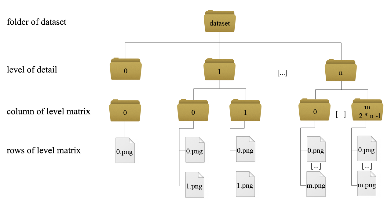
WMTS
In WMTS (more information) a multidimensional dataset of a terrain can be integrated very easy. For every level of detail a new matrix of tiles is required. Every level has its own folder. So if you want to get five different levels of detail in your application, five folders must exist, numbered from 0 to 4. The detail from level to level grows up by a factor of four. Into the folders for the levels, subfolders that describe the columns of the matrix have to be inserted. On level 0 you only have one column, represented through the folder with the name 0. In the next level you have two columns named 0 and 1, growing up by a factor of two from level to level. In the subfolders you place the images that represent the tiles data. There must be as much images as subfolders. On level 0 you only have one image that represents the whole terrain data. On level one exist two subfolders. Every subfolder has to include two images, on the next level four per subfolder and so on. The following figure (figure 1) shows the addressing-scheme:
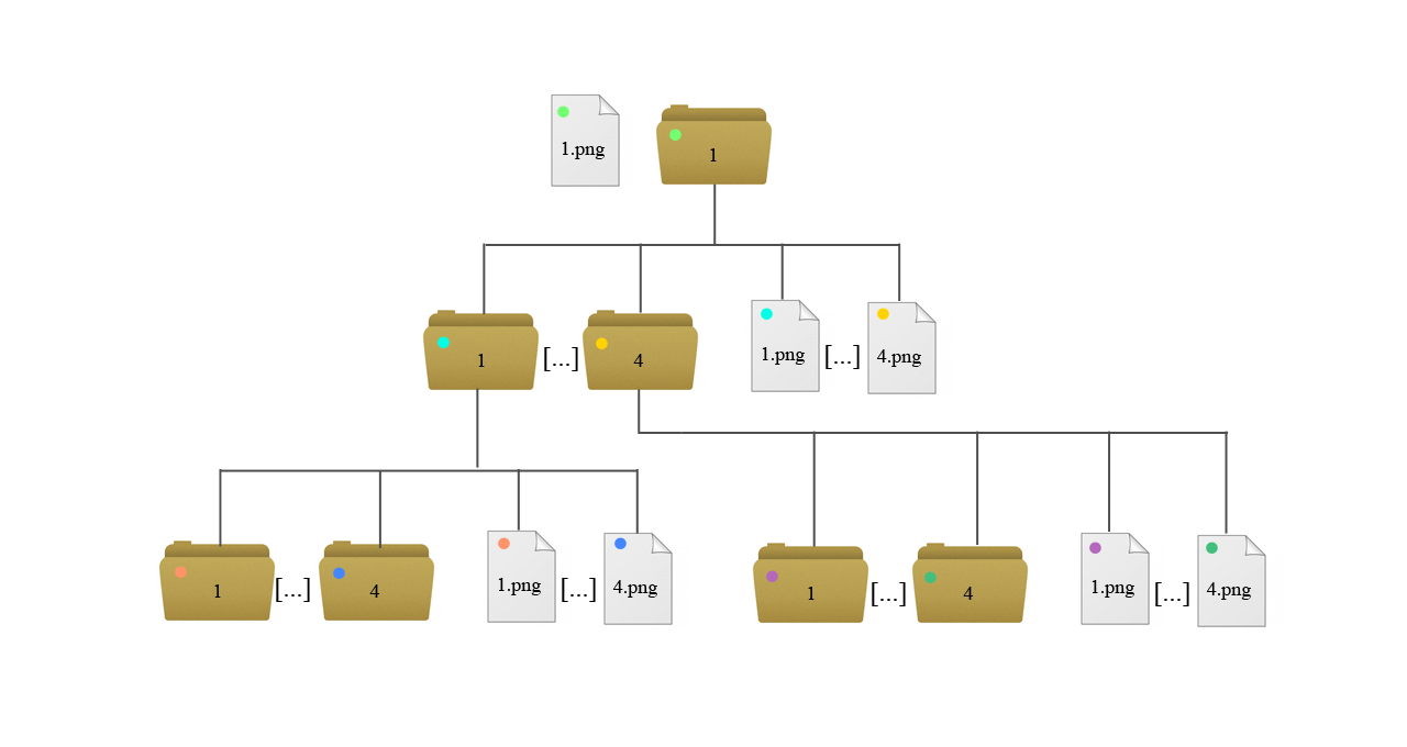
TREE
The TREE addressing-scheme is as easy as the WMTS addressing scheme. Every level in the tree defines a level of detail of the terrain. On level 0 we have an image (1.png) that represents the terrain in the worst quality. It has a folder that has its number as name (1). In this folder we find four images where all four images together represent the whole terrain. The resolution grows up every level by a factor of four. Every image has its folder that always includes four images with the next finer resolution quality. If an image has no folder, the final resolution quality has reached. The position of the images for a finer resolution is as follows:
- 1.png: top left
- 2.png: bottom left
- 3.png: top right
- 4.png: bottom right
Hints for a self-made dataset construction
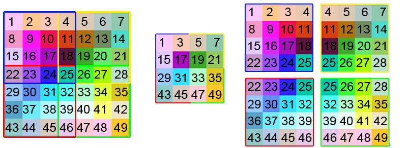
To reconstruct a 3D-Terrain from a WMTS conform dataset a special arrangement of the pixels in the images of the WMTS dataset is required. Neighboring tiles have to share the pixels on the boundaries. The figure on top of this subsection shows on the left the original image, in the middle the image of level 0 of the final dataset and on the right the four images of level 1. Furthermore the resolution of every image of the final dataset must be of the size 2n + 1, where n is the value of the size attribute of a tile in the BVHRefiner node. In the example of Puget Sound on top of this tutorial a value of ‘64 64’ is chosen for every tile as size attribute. So on the dataset, every image has to be of the size ‘129 129’. This is a condition for the algorithm to prevent cracks on the mesh representation.
Using the BVHRefiner Dataset Converter:
The BVHRefiner Dataset Converter is a tool to produce a WMTS or TREE conform dataset from single image. This is only a test application and can not handle arbitrary picture sizes.
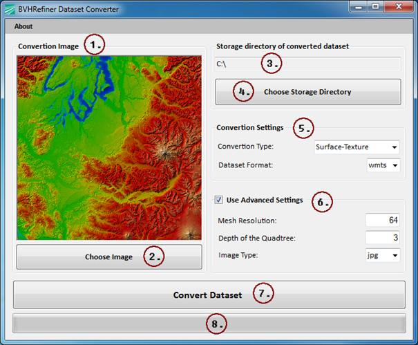
- Representation of the original image
- Opens a file dialog where the source image can be chosen
- Represents the path where the final dataset should be stored
- Opens a folder dialog where the storing path of the final dataset can be chosen
- Convertion settings: a) Convertion Type: Surface-, Displacement- or Normal-Dataset, b) Dataset-Format: Currently supported dataset formats (WMTS, TREE)
- Advanced Settings (are calculated automatically, but can be changed if required): a) Mesh Resolution: Resolution of a tile in the x3dom-application, b) Depth of the Quadtree: The depth of the final dataset (levels of detail), c) Image Type: The image format of all images in the final dataset (jpg, png, gif)
- Starts the convertion of the original source image into the tiled dataset
- Current progress of the convertion
Download .NET based BVHRefiner Dataset Converter:
- Windows 7 x86: BVHRefiner Dataset Converter x86
- Windows 7 x64: BVHRefiner Dataset Converter x64
- Source Code: BVHRefiner Dataset Converter Source
Application prototypes
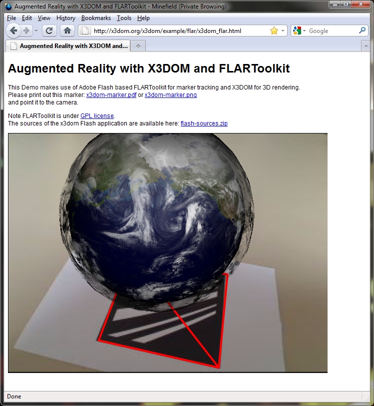
Flash + AR / X3DOM Mashup
This tutorial describes how to create a simple desktop augmented reality scene. We are using Adobe Flash based FLARToolkit for marker tracking and X3DOM for rendering of the 3D scene. By Jens Keil and Michael Zoellner.
At a glance
The tutorial shows the first online Augmented Reality application with Plugin-free hardware accelerated rendering on a GPU. Having the advantages of browser-supported WebGL technology, there is no need to download any kind of plug-in anymore to create Augmented Reality inside web browsers. Its a fast, simple and declarative way to integrate 3D content into HTML and bases on well known and documented standards, like HTML 5, CSS and JavaScript.
Although the tracking still uses Adobe Flash, its modular enough to change and switch tracking as soon as there are native standards for camera access available.
How does it work?
Our FLARToolkit marker tracker shows the webcam in the background and sends a model view matrix of the recognized marker to a Javascript function in the HTML file. From there the MatrixTransform around a bunch of 3D objects in the X3D scene is set with these values.
Setting up FLARToolkit marker tracker
Don’t worry. You don’t need the Flash IDE or any Actionscript knowledge for this tutorial. We are providing a compiled FLARToolkit marker tracker ready for including into an HTML page. It consists of the compiled SWF file (x3domflartoolkit.swf) and a Data folder with the camera parameters (camera_para.dat) and the marker pattern (x3dom.pat). You can change the marker by creating a new one with the pattern generator, putting the results into the Data folder and renaming it to x3dom.pat. Please note that you should keep the generator’s default values for marker resolution and segment size of 16×16 and 50% in order to work properly.
Including the FLARToolkit marker tracker
The compiled SWF is included via object and embed tags into the HTML page. It calls the Javascript function:
set_marker_transform(value)
as soon as it recognizes a marker in the video. The exchanging values include the marker’s position and orientation. As mentioned, they are used to set the 3D object’s position and rotation.
A simple 3D Scene
The demo scene shows a simple AR application: The earth globe, which hovers above the marker. A second layer shows the actual clouds surround the whole planet; live data loaded into the 3D scene.
Our demo is declared in HTML and structured in several divisions. Both, the 3D content and the compiled SWF, are grouped inside two several <Div /> nodes. The layer containing the 3d markup is styled with CSS and positioned on top of the compiled flash movie. Note that both have to have the same size and position in order to achieve a well augmentation effect.
Then, we set up a <MatrixTransform /> node, which groups every 3D object we want to be positioned on the marker. Inside we declare a simple <Sphere /> geometry and texture it with a png file of earth’s appearance. Around the first one, we place a second <Sphere /> object at the same position but with a larger scale and texture it with the transparent cloud data.
The basic structure
<x3d>
<scene>
    <viewpoint fieldOfView='0.60' position='0 0 0'></viewpoint>

     <matrixtransform id="root_transform">
             <transform  translation="0 0 20" scale="50 50 50"
             rotation="0 1 0 3.145">
                     <transform def="earth" rotation="1 0 0 -1.57">
                             <shape>
                                     <appearance>
                                             <imageTexture url="some_texture.jpg">
                                             </imageTexture>
                                     </appearance>
                                     <sphere></sphere>
                             </shape>
                     </transform>
                     <transform def="clouds" rotation="1 0 0 -1.57"
                     scale="1.1 1.1 1.1">
                             <shape>
                                     <appearance>
                                             <imageTexture url="some_texture2.jpg">
                                             </imageTexture>
                                     </appearance>
                                     <sphere></sphere>
                             </shape>
                     </transform>
             </transform>
     </matrixtransform>
</scene>
</x3d>
You don’t need to calibrate your webcam. All of this is handled by the tracker’s camera_para.dat file. Hence, our <Viewpoint />, i.e. our 3D camera, is fixed in its fieldOfview 0.6 and position of 0. The tracker’s values only change and transform our 3D objects; not the camera.
The Javascript functionality
After declaring the 3D content, we add the Javascript code, that handles the data exchange between the Flash based marker tracking and our 3D scene.
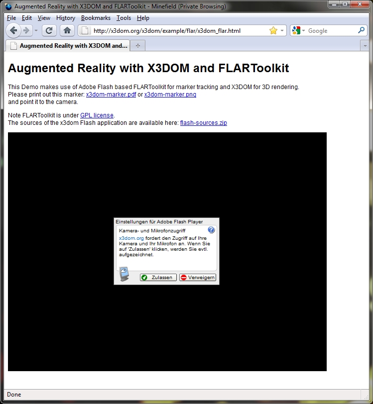
First, we declare a function that hides the X3DOM canvas with the 3D content after the document has loaded. The user needs to allow the Flash tracker to access his camera by clicking a button. This is not possible, when x3dom is rendered on top at start up. As soon as the user confirmed and the marker is detected, we show the 3d content up again.
Our code:
var show_canvas = false;

 // Hide x3dom canavs on page load
 $(document).ready(function() {
    $('#topLayer').hide();
    show_canvas = false;
 });

// Show x3dom canvas again
// function is triggered inside set_marker_transform()
function show_x3dom_canvas(){
    $('#topLayer').show();
    show_canvas = true;
}
Lets take a closer look to the data exchange between X3DOM and the optical tracking:
We declare the set_marker_transform(value) function, which is expected by and triggered from inside the flash tracker. The function sets the new values for the MatrixTransform’s position and rotation. Then we fetch the root MatrixTransform node
var root_transform = document.getElementById('root_transform');
and update the values with the setAttribute(attribute, value) function
root_transform.setAttribute('matrix', q.toString());
Since the tracking triggers new values for every (video) frame, the position is updated as long as the marker is detected. Note, that we also need to convert the received marker values, since X3DOM’s and the tracking’s coordinate system don’t match.
Our code:
//This function is triggered by flash based tracking
function set_marker_transform(value) {
var q = value;
var root_transform = document.getElementById('root_transform');

// if not enabled, show x3dom canvas
if(!show_canvas)
    show_x3dom_canvas();

// Convert rotation form left to right handed coordinate system
// mirror z
q[2][3] = -q[2][3];
q[0][2] = -q[0][2];
q[1][2] = -q[1][2];
q[2][0] = -q[2][0];
q[2][1] = -q[2][1];

// update the grouped 3d object's matrixTranform
root_transform.setAttribute('matrix', q.toString());
}
The tracking also gives feedback when the marker is lost. If you want to work with this information, just declare and use this function inside your Javascript:
function on_marker_loss(value){
    //marker not detected anymore, do something
}
Trouble shooting
Sometimes the 3D content doesn’t show up. This may have two reasons: Be sure you are using a browser who supports WebGL. Also texture loading may take a bit longer and hence may take X3DOM several seconds until the geometry shows up.
You can also control if the marker tracking is working: Check, whether there is a red outline around your marker. If not, ensure the marker is on a plane surface, not occupied and there is enough ambient light.
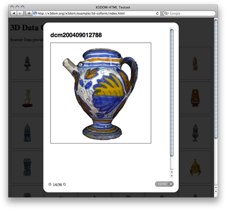
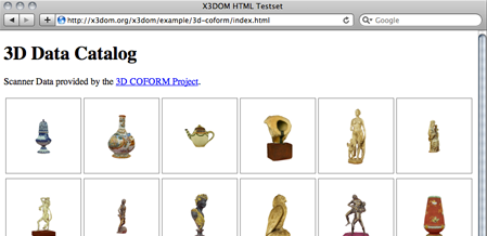
3D Lightbox Gallery of Historical Objects
This tutorial describes how to load arbitrary 3D geometry inside your web page with x3dom. We are going to develop an online catalog of 3D objects, that popup inside our page using the popular lightbox overlay principle (click here for the demo). In our case, the 3D objects are X3D files of 3D scanned historical objects. By Jens Keil.
Generating the grid
Our main page is only the overview of all objects. Hence, we are going to generate a grid with thumbnail images of our objects. We link these images to a second page with the X3DOM content. Since we have 36 objects our grid consists of 6 rows and 6 columns. Let’s use a table for that.
<table id="demo_table" class="gallery clearfix >
  <tr>
    <td><a href="external_html_page"><img /></a></td>
  </tr>
</table>
As mentioned, our 3D content is displayed inside a lightbox popup. This is a JavaScript based script that is normally used to overlays images inside the current web page. In our case, we are going to overlay a external page with the 3D object in it. We have used the prettyPhoto lightbox version of Stephane Caron, since it features the iframes which we need to load a second HTML file into our main page.
In order to tell the script that our linked content should be opened inside the overlay, we add some query parameters at the end of the URL. For example:
<a href="dcm200310301737.html?iframe=true&width=500&height=600"
   rel="prettyPhoto[iframe]" />
Having finished to set up the grid, we initialize the lightbox script after the table definition:
<script type="text/javascript" charset="utf-8">
    $(document).ready(function(){
        $(".gallery a[rel^='prettyPhoto']").prettyPhoto(
            {theme:'light_rounded'});
        });
</script>
Setting up the 3D object’s HTML file
Now, let’s take a look on the inlined page. We have such a page for every 3D object inside our grid. First, we export the scanned data into the X3D file format. Then we convert the X3D file into a X3DOM/HTML file (see Generic 3D data conversion).
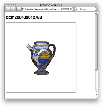
Our X3D decoded 3D content is inside the generated HTML now. We may add a headline or some textual explanation here; indeed, even any other media we’d like to be displayed inside our lightbox overlay. Note, that adding the script node with a link to x3dom.js at the end is doing all the magic: from declarative X3D/HTML5 to visual 3D content inside your web page.
<html>
  <head></head>
  <body>
    <h1>dcm200409012807</h1>
    <x3d id='someUniqueId' showStat='false' showLog='false' x='0px' y='0px' width='400px' height='400px'>
      <scene DEF='scene'>
        <worldInfo title='dcm200409012807'></worldInfo>
        <navigationInfo headlight='true' type='"EXAMINE"'></navigationInfo>
        <directionalLight on='false' ambientIntensity='1' intensity='0'></directionalLight>
        <transform DEF='ORITGT' rotation='1 1 1 -2.094'>
          <shape>
            <appearance>
              <imageTexture url='"dcm200409012807_texture.0.jpg"'></imageTexture>
            </appearance>
            <indexedFaceSet texCoordIndex=' ... ' />
              <coordinate DEF="COORD" point=' ... ' /></textureCoordinate>
            </indexedFaceSet>
          </shape>
        </transform>
        <background skyColor='1 1 1'></background>
        <viewpoint position='0 0 4'></viewpoint>
      </scene>
    </x3d>
    <script type='text/javascript' src='../x3dom.js'></script>
  </body>
</html>
Summary
This tutorial explained how to generate a grid of 3D object inside a web page. Clicking on a thumbnail image opens the 3D object inside a lightbox popup within the current page. Rendering as well as basic navigation is handled by the X3DOM Javascript back end.
Culling
This tutorial explains the different parameters to adjust x3doms integrated culling techniques for your personal needs on quality and performance.
The Environment-Bindable
All relevant parameters are included in the new Environment-Bindable. To change it’s settings it has to be added to the scene explicitly. For each culling technique there exists a boolean flag to enable/disable it and a list of more detailed settings if applicable. Each of the following sections explains the usage of a technique and it’s parameters. Their combination can lead to very different results which allows explicit performance tuning for a specific scene.
<environment frustumCulling='true' smallFeatureCulling='true'>
</environment>
View Frustum Culling
The most common culling technique is the viewfrustum culling controlled by the viewFrustumCulling flag. The bounding volumes of the nodes are tested to be intersecting the frustum defining the current view. The nodes of the scene are traversed recursively reusing already calculated intersection if possible. It is the only technique which is not dependent on additional parameters.
| Setting | Usage | Values |
|---|---|---|
| frustumCulling | (de-)activate the culling technique | [true;false] |
Small Feature Culling
Using the smallFeatureCulling flag this technique is activated. For each node the amount of pixels is calculated it’s bounding volume would cover in screen space. If the coverage is below the smallFeatureThreshold parameter the node (and subsequent shapes) is culled.
| Setting | Usage | Values |
|---|---|---|
| smallFeatureCulling | (de-)activate the culling technique | [true;false] |
| smallFeatureTreshold | cull objects covering less pixels than treshold | [0..*] |
Occlusion Culling *
Being the most complex supported culling method, occlusion culling is triggered by the occlusionCulling flag. The scene is traversed using the “Coherent Hierarchical Culling++” algorithm and based on the triggere occlusion queries the screen space coverage not occluded by other nodes is tested. A node is only drawn if its coverage is higher than the occlusionVisibilityTreshold.
| Setting | Usage | Values |
|---|---|---|
| occlusionCulling | (de-)activate the culling technique | [true;false] |
| occlusionVisibilityTreshold | cull objects covering less pixels than treshold due to occlusion | [0..*] |
Low Priority Culling
This is the only supported comparison-based culling technique. Triggered by the lowPriorityCulling the nodes which passed all previous (activated) culling techniques are sorted by their priority. Afterwards the part of this list defined by the lowPriorityTreshold is removed. At the moment the screen-space coverage is used as priority, later on there will be a more sophisticated calculation allowing the user to set priorities to mark his or her personally important nodes. Therefore by now the priority culling is very similar to the small feature method but culling a relative amount instead of comparing to an absolute threshold.
| Setting | Usage | Values |
|---|---|---|
| lowPriorityCulling | (de-)activate the culling technique | [true;false] |
| lowPriorityThreshold | draw only objects within threshold fraction of priority sorted list | [0..1] |
Tesselation Detail Culling
The possibiliy of using this culling technique completely depends on the support of each drawable. Up to now only the POP-Geometry natively supports it. As long as the resulting error stays within the amount of pixels defined by tesselationErrorThreshold the tesselation of the mesh is lowered to certain degree. It can be enabled using the flag tesselationDetailCulling.
| Setting | Usage | Values |
|---|---|---|
| tesselationDetailCulling | (de-)activate the culling technique | [true;false] |
| tesselationErrorTreshold | use mesh simplification having lower error than threshold | [0..*] |
(* : Not fully implemented yet)
Elsewhere
If you can read German, there is also some German content available on our website:
Camera Navigation
X3DOM provides some generic interaction and navigation methods. Interactive objects will be handled by HTML-like events. Navigation can be user-defined or controlled by specific predefined modes.
Currently X3DOM supports the following interactive navigation modes:
- Examine
- Walk
- Fly
- Look-at
- Look-around
- Game
- Helicopter
Non-Interactive movement encompasses the functionality of:
- Resetting a view
- Showing all
- Upright view
Interactive camera movement
Examine
Activate this mode by pressing the "e" key.
| Function | Mouse Button |
|---|---|
| Rotate | Left / Left + Shift |
| Pan | Mid / Left + Ctrl |
| Zoom | Right / Wheel / Left + Alt |
| Set center of rotation | Double-click left |
Walk
Activate this mode by pressing the "w" key.
| Function | Mouse Button |
|---|---|
| Move forward | Left |
| Move backward | Right |
Fly
Activate this mode by pressing the "f" key.
| Function | Mouse Button |
|---|---|
| Move forward | Left |
| Move backward | Right |
Helicopter
Activate this mode by pressing the "h" key.
To look downwards/upwards and to move higher/lower use the keys (8/9 and 6/7).
| Function | Mouse Button |
|---|---|
| Move forward | Left |
Look at
Activate this mode by pressing the "l" key.
| Function | Mouse Button |
|---|---|
| Move in | Left |
| Move out | Right |
Game
Activate this mode by pressing the "g" key.
To look around (rotate view) move the mouse.
| Function | Key |
|---|---|
| Move forward | Cursor up |
| Move backward | Cursor down |
| Strafe Left | Cursor left |
| Strafe Right | Cursor right |
Non-interactive camera movement
| Function | Key |
|---|---|
| Reset view | r |
| Show all | a |
| Upright | u |
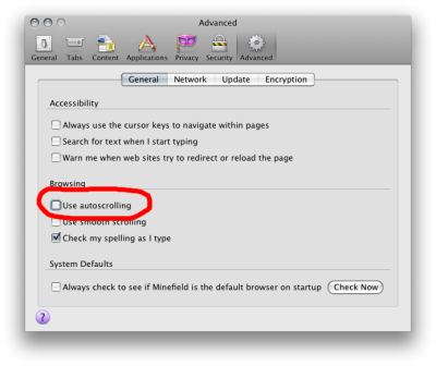
Mid-Button troubleshooting
If the web page has scroll bars and autoscrolling is enabled, Mid-Button currently does not work correctly. As a workaround, you can disable autoscrolling by unchecking the Use autoscrolling checkbox in the Firefox browser options, as is shown in the screenshot below (for the Firefox case).
Configuration
The X3D element supports attributes and a param tag which allows to set configuration for the runtime.
Usage
The param element behaves just like any other HTML element. It must be nested below the X3D element. For XHTML you can use the self-closing syntax, for HTML a closing tag is mandatory:
<x3d>
    <param name="showLog" value="true" ></param>
    <scene>
        ...
    </scene>
</x3d>
Note: The param tag used to live as child of the scene element. This behavior has been changed with version 1.3 of X3DOM. You will get a deprecation warning and support will be removed in 1.4.
Options
The following table lists the parameters currently supported.
| Parameter | Values | Default | Description |
|---|---|---|---|
| showLog | true, false | false | Hide or display the logging console |
| showStat | true, false | false | Hide or display the statistics overlay |
| showProgress | true, false, bar | true | Hide or show the loading indicator. The default indicator is a spinner. The value ‘bar’ will use a progress bar. |
| PrimitiveQuality | High, Medium, Low, float | High/1.0 | Render quality (tesselation level) for Box, Cone, Cylinder, Sphere. |
| component | String (i.e. Geometry3D) | none | Name of the component to load |
| loadpath | String (i.e. nodes/) | none | The path or URI where to find the components |
| disableDoubleClick | true,false | false | Disables the default double click action on viewarea |
| disableRightDrag | true,false | false | Disable mouse right button drag and mouse wheel |
Troubleshooting
As with most software systems, something can go wrong. But fear not. There are a couple of things you can check and try. You’ll find some hints and tips here.
Common problems
I am not seeing anything
Assuming we are not dealing with an electrical or vision problem:
- Check if your HTML and X3D code is correct
- If you are using the HTML5 doctype make sure all X3D tags are properly closed. You can not use “self-closing” syntax. Instead you need to close the tag explicitly: <color ...></color> NOT <color ... />
- For the HTML part, swing by the W3C validator to check for syntax errors
There are weird chars or some gobbledygook on my web page
This is most likely an encoding problem or errors generated by using unsuited editors or HTML export tools (looking at you Word). Gobbledygook may be caused by improperly closed tags (see above).
- Check if you file encoding is OK. UTF-8 is recommended unless otherwise required.
- Use a HTML meta to denote the file encoding and make sure your file endcoding matches your meta tag.
- In case you are serving your files from a web server: make sure the server sets proper HTTP headers (especially mimetype and encoding) and middleware does not alter the file encoding (PHP et al. are sources for messing up multi-byte encodings). Again, maintaining UTF-8 throughout is a sensible choice (also read this).
How to ask Questions
In order to analyze and debug your problem, please be more specific about the nature of your problem. Before you sit down and write a mail or forum post, it is helpful to ask yourself these questions and include this info in your question/report:
- What exactly is not working?
- Is it really an error or are you just unhappy with aesthetics?
- What errors do you get?
- Can you reproduce this behavior in an isolated testcase?
- What did you try to solve your problem?
The following info is genuinely helpful in analyzing your problem:
- OS, Version, Architecture
- GPU type, driver versions
- Output of about:gpu in Chrome
- Browsers and versions you tried and the results
- Log output of X3DOM (javascript console)
- You can generate some of the information here http://doesmybrowsersupportwebgl.com/
Also note that hot-linking x3dom.css/js should only be used for testing and development. Once you deploy your site, it is best to copy those files over to your server or a CDN. We can not guarantee that those URLs are stable and our network bandwidth is rather limited.
This his also a helpful page and a good read as well: http://catb.org/~esr/faqs/smart-questions.html
Reference
If you are looking for information on a specific function, class or method, this part of the documentation is for you.
API
The X3DOM API is currently split into two parts:
- Runtime
- Docs
The runtime api provides progrmmatic live access to the system. The Documnetation API allows to dynamically generate documentation artifacts embedded derived from the source code (e.g. a list of loaded nodes).
Runtime
The X3DOM runtime API provides proxy object to programmatically read and modify runtime parameters. The runtime proxy is attached to each X3D element and can be used in the following manner:
var e = document.getElementById('the_x3delement');
e.runtime.showAll();
e.runtime.resetView();
...
Some methods, like the x3dom.ready() function need to be called before the proxy object can be initialized. You can still override these functions globally. In order to provide you with the means to scope your actions to a specific X3D element, the methods receive the X3D element they are working on as first parameter:
x3dom.ready = function(element) {
    if (element == target_element) {
        // do something
    }
};
- noBackendFound()
This callback is executed once the system initialized and is not ready to render the first time because there is no backend found. By default this method noop. You can however override it with your own implementation.
- x3dom.runtime.noBackendFound = function() {
- alert(“No backend, what a bummer.”);
}
It is important to create this override before the document onLoad event has fired. Therefore putting it directly under the inclusion of x3dom.js is the preferred way to ensure overloading of this function.
Please note that this does not account for a installed, but disabled Flash plugin.
- ready()
This method is called once the system initialized and is ready to render the first time. It is therefore possible to execute custom action by overriding this method in your code:
x3dom.runtime.ready = function() {
    alert("About to render something the first time");
};
It is important to create this override before the document onLoad event has fired. Therefore putting it directly under the inclusion of x3dom.js is the preferred way to ensure overloading of this function.
- enterFrame()
This method is called just before the next frame is rendered. It is therefore possible to execute custom actions by overriding this method in your code:
var element = document.getElementById('my_element');
element.runtime.enterFrame = function() {
    alert('hello custom enter frame');
};
During initialization, just after ready() executed and before the very first frame is rendered, only the global override of this method works.
If you need to execute code before the first frame renders, it is therefore best to use the ready() function instead.
- getActiveBindable(typeName)
Arguments: - typeName (string) – A valid Bindable node (e.g. Viewpoint, Background,
Returns: Active dom element
This method returns the currently active bindable DOM element of the given type.
For example:
var element, bindable;
element = doucment.getElementById('the_x3delement');
bindable = element.runtime.getActiveBindable('background');
bindable.setAttribute('set_bind', 'false');
- nextView()
Navigates to the next viewpoint.
- prevView()
Navigates to the previous viewpoint.
- viewpoint()
Returns the current viewpoint.
- viewMatrix()
Returns: Matrix object Returns the current view matrix object.
- projectionMatrix()
Returns: Matrix object Returns the current projection matrix object.
- getWorldToCameraCoordinatesMatrix()
Returns: Matrix object Returns the current world to camera coordinates matrix.
- getCameraToWorldCoordinatesMatrix()
Returns: Matrix object Returns the current camera to world coordinates matrix.
- getViewingRay(x, y)
Arguments: - x – Layer x position
- y – Layer y position
Returns: Line object, from camera origin through (x, y)
Returns the viewing ray for a given (x, y) position on the canvas.
- getWidth()
Returns: Width in pixels Returns the width of the canvas element.
- getHeight()
Returns: Height in pixels Returns the height of the canvas element.
- mousePosition(event)
Arguments: - event – The event
Returns: [x,y] position
Returns the 2d canvas layer position [x,y] for a given mouse event, i.e., the mouse cursor’s x and y positions relative to the canvas (x3d) element.
- calcCanvasPos(wx, wy, xz)
Arguments: - wx – World coordiante X axis
- wy – World coordiante Y axis
- wz – World coordiante Z axis
Returns: Array with 2D corrdinates (x,y)
Takes world coordinates (x,y,z) of the scene and calculates the relating 2D X/Y coordinates respective to the canvas the scene is rendered on.
This allows you to relate 3D world coordinates to a specific position on the 2D canvas. This can be usable to position a HTML element over the canvaas (like a hint window for exmaple).
- calcPagePos(wx, wy, xz)
Arguments: - wx – World coordiante X axis
- wy – World coordiante Y axis
- wz – World coordiante Z axis
Returns: Array with 2D corrdinates (x,y)
Takes world coordinates (x,y,z) of the scene and calculates the relating 2D X/Y coordinates relative to the document the scene is rendered in.
- calcClientPos(wx, wy, xz)
Arguments: - wx – World coordiante X axis
- wy – World coordiante Y axis
- wz – World coordiante Z axis
Returns: Array with 2D corrdinates (x,y)
Takes world coordinates (x,y,z) of the scene and calculates the relating 2D X/Y coordinates relative to the window the scene is rendered in.
- getScreenshot()
Returns: URL to image Returns a Base64 encoded data URI containing png image consisting of the current rendering. The resulting URL will look similar to this:
data:image/png;base64,iVBORw0KGgo...
The browser will interpret this as a PNG image and display it. A list of browsers which support data URI can be found here.
The following example illustrates the usage:
var url = ...runtime.getScreenshot();
var img = document.createElement("img");
img.src = url;
...
- lightMatrix()
Returns: The current light matrix Returns the current light matrix.
- resetView()
Navigates to the initial viewpoint.
- lightView()
Returns: True if navigation was possible, false otherwise. Navigates to the first light, if any.
- uprightView()
Navigates to upright view.
- showAll()
Zooms so that all objects are visible.
Arguments: - axis (string) – the axis as string: posX, negX, posY, negY, posZ, negZ
- showObject(obj, axis)
Arguments: - obj – the scene-graph element on which to focus
- axis – the axis as string, one of: posX, negX, posY, negY, posZ, negZ
Zooms so that a given object is fully visible.
- getCenter(domNode)
Arguments: - domNode – the node for which its center shall be returned
Returns: Node center or ‘null’ if donNode is not a Shape or Geometry
Returns the center of a X3DShapeNode or X3DGeometryNode as SF3Vec3f object.
- getCurrentTransform(domNode)
Arguments: - domNode – the node for which its transformation shall be returned
Returns: Transformation matrix (or null no valid node is given)
Returns the current to world transformation of a given node. If no valid node is given null is returned.
- debug(show)
Arguments: - show (boolean) – true/false to show or hide the debug window
Returns: The current visibility status of the debug window (true/false)
Displays or hides the debug window. If the parameter is omitted, the current visibility status is returned.
Returns: A string representing the active navigation type. A readout of the currently active navigation type.
- examine()
Switches to examine mode.
- lookAt()
Switches to lookAt mode.
- lookAround()
Switches to lookAround mode.
- walk()
Switches to walk mode.
- game()
Switches to game mode.
- helicopter()
Switches to helicopter mode.
- resetExamin()
Resets all variables required by examin mode to init state
- togglePoints()
Toggles points attribute
- pickRect(x1, y1, x2, y2)
Arguments: - x1 – x1 coordinate of rectangle
- y1 – y1 coordinate of rectangle
- x2 – x2 coordinate of rectangle
- z2 – y2 coordinate of rectangle
Returns: Array of shape elements
Returns an array of all shape elements that are within the picked rectangle defined by (x1, y1) and (x2, y2) in canvas coordinates
- pickMode(options)
Arguments: - options (object) – An object of properties i.e. options = {‘internals’: true}
Returns: The current intersect type value suitable to use with changePickMode
Get the current pickmode intersect type. If the option ‘internals’:true is provided, the interal representation is returned.
- changePickMode(type, options)
Arguments: - type (string) – The new intersect type: idbuf, color, textcoord, or box.
Returns: True if the type hase been changed, false otherwise
Alter the value of intersct type. Can be one of: idbuf, color, textcoord, box. Other values are ignored.
- speed(newSpeed)
Arguments: - newSpeed (float) – The new speed value (optional)
Returns: The current speed value
Get the current speed value. If parameter is given the new speed value is set accordingly.
- statistics(mode)
Arguments: - mode (boolean) – true/false to enable or disable the stats info
Returns: The current visibility of the stats info (true/false)
Get or set the visibility of the statistics information. If parameter is omitted, this method returns the visibility status as boolean.
- isA(domNode, nodeType)
Arguments: - domNode (object) – the node to test for
- nodeType (string) – node name to test domNode against
Returns: True or false
Test a DOM node object against a node type string. This method can be used to determine the “type” of a DOM node.
- processIndicator(mode)
Arguments: - mode (boolean) – true to show indicator, false to hide
Returns: The current visibility of the process indicator info (true = visible, false = invisible)
Enable or disable the process indicator. If parameter is omitted, this method only returns the the visibility status of the statistics info overlay.
- backendName()
Returns: The current render backend name as string Returns the currently used render backend name.
- properties()
Returns: Properties object Returns the properties object of the X3D element. This holds all configuration parameters of the X3D element.
Docs
The documentation API is a set of static functions (object literal) which allows to obtain documetantion related information form the library:
var info;
var info_pane;
info = x3dom.docs.getNodeTreeInfo();
info_pane = getElementById('infopane');
info_pane.innerHTML = info;
The documentation module is optional and only provided with the x3dom-full package.
- getNodeTreeInfo()
Returns: A div element containin the nodes and link to specification Return a div filled with nodes implemented and link to documentation. This can be used to build interactive documentation.
Note: Unstable API method. Name and retrun value might change
- getComponentInfo()
Returns: A div element containin the nodes and link to specification, grouped by components and sorted alphabetically Return a div filled with nodes implemented and link to documentation. This particular method returns the the nodes grouped by components and sorted alphabetically.
This can be used to build interactive documentation.
Note: Unstable API method. Name and retrun value might change
Nodes
The following list is a live generated node list. You can only see this information in a browser. If you are viewing this documentation in other formats, please visit the Node Type Tree document and click on a Node to view the related X3D specification.
Warning
Not all nodes and fully implemented right now.
Components
X3DOM features a component system which allows you to load parts of the system at runtime. Components are a set of X3D nodes logically grouped together and put into a file. For example, the Geometry2D component consists of nodes named Arc2D, Circle2D, etc and is stored in a file named Geometry2D.js. Those components are then further grouped into profiles which combine them for specific application domains. For example there is a core profile, an immersive profile, Interchange profile, and so on. Except for the full profile, profiles are an abstract concept and not reflected in file layout.
While logical grouping like this falls mostly into the category of code organization, it can be utilized to load only the parts you need for your application. With X3DOM there are two versions of the library in the distribution package:
- the standard full profile file: x3dom-full.js
- the core containing only basic nodes: x3dom.js
You will find these files in release directory of X3DOM. Note that this is currently the development version of X3DOM. http://x3dom.org/download/dev/.
The full profile contains all the nodes of the official X3D specification, as far as they are implemented in X3DOM, merged into one file.
When using x3dom.js (core) you may need to either include or dynamically load additional nodes you need to render your model. This can be achieved by including the required node implementations files in your HTML using the <script> tag, or by instructing X3DOM to load the components at runtime.
By default X3DOM comes with the following additional nodes:
- Geometry2D
- VolumeRendering
- Geospatial
If you are using x3dom.js and you need to load the nodes above, you can use one of the methods described below.
Note: It is recommended that you use the full X3DOM version (x3dom-full.js) in production environments - unless there is a very specific reason not to. The full version is compacted, optimized and in almost all cases the right way of including X3DOM. Should you opt for using the methods described here, you are trading negligible saving in initial download size for a much slower loading system, additional requests, way more complicated setup and maintenance, inability to use the browsers cache, problems with firewalls, proxy servers, CORS issues, CDNs, and not being able to run run locally without a web server.
Static component loading
This technique works by manually including the X3DOM core library plus the components you need for rendering your model. Your resulting HTML could look like this.
<script src="x3dom.js"></script>
<script src="Primitives2D.js"></script>
<script src="Other.js"></script>
Benefits of this approach:
- static loading (no ajax requests)
- works locally without a web server instance
Drawbacks of this approach:
- more requests are required
- more files to manage in complex setups (could be somewhat mitigated using something like Sprockets)
This is essentially how we build the full profile library, except that we deliver everything in one optimized file. When you write your own components, you can use this method - it also works with the full profile X3DOM file.
When to use this method:
- When you write your own components
- During development and testing
Dynamic component loading
X3DOM features a mechanism to load files at runtime. With this approach it is possible to load anything from anywhere and inject that code into your application. Be aware of this possible exploit when using the technique described here.
Warning
In order to allow dynamic loading of components, you need to tell X3DOM to turn off its security precautions before including the X3DOM library. These precaution prevents the library from executing code that is known to be insecure. Only use this feature if there is absolutely no other option for you.
In order to disable security measures in X3DOM, put the following statement in your document <head> section and before the inclusion of X3DOM:
<head>
  <script>
    X3DOM_SECURITY_OFF = true;
  </script>
  <script src="x3dom.js"></script>
  ...
</head>
Now, dynamic loading components at runtime is enabled and can be used by putting the following parameters in you X3D scene.
<x3d>
    <param name="component" value="Primitives2D,Other"></param>
    <param name="loadpath" value="http://yourserver/path/"></param>
    ...
</x3d>
If loadpath is not set X3DOM tries to load the component from the documents parent URL.
Keep in mind that the dynamic loading of X3DOM components performs an synchronous Ajax request. As such all the limitations of Ajax requests apply, plus the library is blocking your browser until it gets a response.
Drawbacks of this approach:
- load order is important and has to be maintained by developer
- needs a web server running (ajax)
- blocks the browser during loading of files
- code injection possibility high
- needs much more requests
- ajax request caching not really supported
When to use this method:
- never (unless there’s no other feasible way)
Extending X3DOM
In this chapter you will learn how to extend X3DOM with your own nodes which you can load using the methods outlined above. We recommend to use the static loading approach in combination with the core profile x3dom.js. This results in the inclusion of x3dom.js and YourComponent.js which will contain your custom code.
To follow this chapter you need at least basic understanding of the following concepts, principles, or technologies:
- object orientation
- class based object model
- programming in general
- Javascript programming
- the Javascript object model
- XML and HTML5
Object system
In order to register a new node within the X3DOM system, you need to create the equivalent of a class that inherits properties from a superclass. Javascript itself does not implement a class based object model, it provides a prototype model. A prototype based object model can be seen as a superset of a traditional class based model. With a prototype based object system, one can implement a more limited class based system. That is exactly what X3DOM does.
For each node you want to implement in X3DOM you need to call the function:
x3dom.registerNodeType("YourNodeName", "GroupName", definitionObj);
This registers a node within the X3DOM system and provides a hook to the implementation of this class. The first parameter also is the name of the XML tag you are writing code for. The third parameter to registerNodeType is the return value of a call to the X3DOM function:
defineClass(superclassObj, constructorObj, implementationObj);
This function is roughly equivalent to creating a class definition in a language with an traditional class based object system.
Note: The defineClass function resides in the global Javascript namespace whereas the registerNodeType function is nested within the x3dom namespace. This is intentionally so and not a typo.
Hello World
Let’s say we want to implement a custom node which echos a “Hello World” to the console, we first need to decided how the XML should look like. In this case, we simply want another XML tag that looks like this:
<x3d>
  <scene>
    <hello></hello>    <-- this is new
  </scene>
</x3d>
Since there is no Hello node in the X3DOM system nothing happens when we run this X3D in the browser. The <hello> tag is not recognized and therefore ignored by X3DOM. In order to make X3DOM aware of the <hello> tag we need to register a new node with the system and provide an implementation for that node. In order to do so we are using the two function calls described above:
x3dom.registerNodeType(
    "Hello",
    "Core",
    defineClass(x3dom.nodeTypes.X3DNode,
        function (ctx) {
            x3dom.nodeTypes.Hello.superClass.call(this, ctx);
        }, {
              nodeChanged: function() {
                  x3dom.debug.logInfo('Hello World from the console');
              }
        }
    )
);
First, the hello node is registered with X3DOM, the hello node belongs to the core nodes. We then create an implementation object of the type x3dom.nodeTypes.X3DNode, the superclass. We also define a constructor for our node in form of a function object that we pass to the defineClass() function (second positional parameter). The last parameter consists of an object literal containing function definitions for the node API. In this example we implement a function called nodeChanged which will be called by X3DOM anytime there is a change to the node element in the DOM. It is also called when the node is encountered the first time. This is the place where print a message to the console using the X3DOM debug facilities.
The nodeChanged function is not the only function you can pass your implementation. For example, there is a fieldChanged method which is called whenever a attribute in the DOM changes, and you can implement your own methods here.
More
For more examples of nodes, please refer to the source code of the X3DOM nodes. It’s the best way to learn how to deal with the X3DOM node system.
Notes & How-Tos
Design notes, legal information and changelog are here for the interested.
Notes
Different topics of interest. This section should be seen as incubation space for collaboration and ideas. Ultimately things move up to the main documentation.
Loading resources from external servers
Sometimes it is desirable to load resources, like textures, from other locations than your web server. The most common use case being serving textures from a CDN. While technically not a problem, there are security mechanisms in place to prevent injection of malicious code into your application. Browser vendors started to block loading of resources originating from domains unless these resources marked safe by the foreign web server.
The corresponding W3C specification is called Cross-Origin Resource Sharing [CORS2010] and adhered to by most browsers. And in essence, you need to configure the foreign web server to add a HTTP header that marks the resource safe for your domain. Say, your application is served from http://yoursite.org and needs to load resources from http://othersite.org, the webserver of othersite.org needs to set a HTTP header that marks yoursite.org safe for cross site requests. For example:
Access-Control-Allow-Origin: http://yoursite.org
If you don’t care and want to allow access to all users, you can add e.g. the following to your httpd.conf (given you are using Apache2):
<Directory />
    Header set Access-Control-Allow-Origin "*"
    Header set Access-Control-Allow-Headers "Content-Type"
    Header set Access-Control-Allow-Methods "GET, PUT, OPTIONS, DELETE, POST"
</Directory>
An alternative to adhering to the CORS protocol, is to setting up a proxy server forwarding requests to the foreign server in the background. If you can do away with the benefits CDN provides this technique may be a viable alternative.
More information on CORS and setting HTTP headers:
More information on proxy configuration:
Developing locally
While the HTTP headers method presented above is the best practice in production environments, it is unpractical for local development of your application. Fortunately there are a couple of workarounds making you develop with pleasure.
- Use a real web server (e.g. Apache) to deliver your site locally
- Use a web server with proxy module to fetch external resources form a live website
- Use browser flags to disable security measures
The latter one being the most flaky. It is not guaranteed that the browser will support disabling security in the long run. Also strange behaviour in case of magically enabled security after updates in combination with browser caches.
Using a web server
Installing a web server locally and serving your files under the localhost domain is the best way of developing web applications. We also recommend you use this technique when developing with X3DOM. Using a full web stack locally ensures that your browser behaves the same way it would when loading a website over the internet. Requests are sent and received by the browser just like they would in a production environment. It is also the only way to properly test Ajax functionality and HTTP features, like expiry headers.
There are various ways to install a web server on your machine. In case of Mac OS X, Apache is already installed and you can just put your documents in your Site folder.
On Linux there are various ways to install Apache depending on your distribution. Most likely two or three commands should suffice.
Windows users are best served with a package called XAMPP, which also caters various Unix based systems.
Using a web server with proxy pass
What about external resources in local development, I want to develop locally and load textures from textureheaven.net. You could install as system wide proxy server, which processes the request and response to textureheaven.net and adds the correspoding CORS header to the response. Another straight forward way is to leverage the power of what you already have: your local web server.
The setup is more elaborate and out of the scope of this document. Here are some pointer of how to get started.
First you need to confiture your web server to answer requests to textureheaven.net instead of sending those requests to the real textureheaven.net web server. To do so you need to make an entry in your /etc/hosts file so the address does not resolve to the real site but to localhost. Within your web server configuration you now create a virtual host that answers requests to textureheaven.net and proxies them request to the real textureheaven.net site. In order to make this all work, you finally need to add a CORS header to the response (e.g. Access-Control-Allow-Origin: http://localhost)
Sounds too complicated? There’s a shortcut way. But as with all shortcuts, use it with caution.
Disable browser security
If you have all resources locally, there is a shortcut for circumventing the CORS mechanisms. Please use with care.
The Chrome browser allows you to disable a security precaution that prevents you loading resources from disk. Use the following startup parameters:
--allow-file-access-from-files
--allow-file-access
--disable-web-security
Enter the following in your location bar:
about:config
Acknowledge the secuirty warning and enter the following in the filter bar:
fileuri
Look for the option called security.fileuri.strict_origin_policy and set it to false.
| [CORS2010] | Cross-Origin Resource Sharing, W3C, 2010. Available online at http://www.w3.org/TR/cors/ |
+++ Draft +++
Complex models
While X3DOM is very well suited for small models up to a few kilobytes in size, big models can become a major problem. This section takes a look at the different aspects involved and tries to find partial solutions to the problem. The problems can be broken down to the following areas:
- Loading a HTML/X3D file containing a lot of data
- Parsing data into the DOM
- Storing data in memory
And server side:
- I/O when sending big files (sendfile)
- Server stalling because user presses “reload” endlessly when not informed that an operation is in progress and consequently exhausting free server slots.
While most of these problems are inherent to the domain we are moving in, and not X3DOM specific, measures can be taken to optimize loading of large chunks of data, especially cutting down transmission time over the network.
Another, more complex problem, is presented by the way JavaScript and DOM work. There is no manual memory management possible and freeing up memory is left to the garbage collector that runs at intervals out of our control. We can not even manually start garbage collection. And if we could, there is quite some overhead involved in garbage collection.
The only alternative to cope with the memory specific problem is circumventing the DOM entirely parsing. While this somewhat defies the purpose of X3DOM, it may present a viable alternative for performance critical applications. Various techniques and ideas are explored further in the following sections.
It is paramount to keep in mind, no matter how much we optimize, the use of complex models is limited by the following boundaries:
- Memory of client (storing more data)
- Processing power of client machine (parsing more faster)
In the following sections we are presenting various tools and techniques to optimize various aspects of loading big models.
Delivering deflated content (HTTP/1.1)
The most obvious idea is to compress the HTML/XML files. Luckily this is the easiest to implement and will improve performance of loading time significantly. Most web browsers support the deflate algorithms (ZIP) and can handle compressed files on the fly. The web server is configured to compress HTML files before delivering them to the client. By means of setting the HTTP (Accpet-Encoding), header, denoting a compressed file arrives, the client can act on this information and decompress the deflated file on the fly. Any browser that supports the HTTP/1.1 should be able to handle deflated input.
In order to enable your webserver to compress the files during transport, the configuration needs to be alterd. How to achieve this can be found in you web server documentation. For exmaple:
If you are using a different web server, refer to its documentation.
Benefits
It is considered good practice for web development to enable in-memory compression for text resources like HTML, CSS, JS. Tests showed that file size can be reduced to about 50%. Transmission time should be typically cut in half. For exmaple, the vary large model of the walking soldier () is about 13MB in size. Using GZIP compression, this model is only 5.2MB big.
Drawbacks
This method does not present us with any significant drawbacks.
A slight overhead on server- and client-side processing power is inherent with on-the-fly compression. Caching techniques of web servers and browser mitigate the small performance hit of on-the-fly compression.
An actual benchmark of decompressing the soldier model has not yet been conducted. However the ventured guess is that the savings of network time outperform the decompression algorithm which runs naively.
For very large files this technique may not be beneficial since the server may block too long during compression or the client, especially with slow clients, may take to long to decompress. This however needs to be verified and tested.
We recommend to enable compression on your web server and only out out if there are performance hits than can be attributed to compression.
Makeing use of browser side caching
- Etags
- Expire headers
- HTML5 offline stuff?
- etc.
Using asynchronous loading (aka Ajax)
X3D inline Ajax
Benefits
Drawbacks
The most significant drawback of the current XMLHttpRequest object implementations is the complete ignorance of the HTTP Accept-Encoding header. While lazy loading geometry data is possible using either the X3D inline element or custom code to load a model and modify the DOM, the lack of compression makes this process rather slow.
Using geometry images
Benefits
- Uses canvas to decode (native speed)
- Circumvents the DOM for better performance
Drawbacks
- Circumvents the DOM
- Use cases limited to simpler geometry?
Web server optimizations
Optimization of a web server is not exactly a core topic of X3DOM. To give you a starting point, we collected some resources that should get you going:
- Apache
- YSlow
- yada, et cetera et al.
Platform Notes
System requirements and browser notes
In order to be able to work with X3DOM, you need a WebGL enabled web browser. We also support different fallback models for browsers not supporting WebGL natively. The best support of features however is only ensured with a browser sporting a WebGL implementation. You can check the status of supported browser here.
Chrome
Recent releases of Chrome require you to enable WebGL. Please use the following command parameters when launching chrome:
--enable-webgl
--use-gl=desktop
--log-level=0
--allow-file-access-from-files
--allow-file-access
The last two options enable the browser to load textures from disk. You will need this if you are developing your site locally.
Platform notes (OS/GPU/Drivers)
While WebGL is supported in most current browsers, there are various little differences in operating system and graphics driver support. We can not discuss any possible OS/GPU/Driver combination here, but you might find some valuable hints if you can not get WebGL up and running on your system. With all systems be sure to use latest drivers for your graphics card and be sure those drivers support the OpenGL standard.
Blacklists
Some GPUs and Driver combinations are blacklisted by browser vendors. In case of strange errors, please check the following lists for:
Windows
Chrome Frame
Currently, the only way to use WebGL with Internet Explorer is by using the Google Chrome Frame plugin. In order to make X3DOM use the WebGL renderer with Internet Explorer, you need to install Chrome Frame and enable it in your HTML or web browser configuration. The most simple way to enable ChromeFrame is to put this line in your HTML head section:
<meta http-equiv="X-UA-Compatible" content="chrome=1" />
Download and furhter reading:
Mac OS X
Safari 5.1+ is supporting WebGL, however you need to enable it in the Developer menu. This menu is invisible by default. Go to “Preferences” (Cmd-,) and select the “Advaned” tab. Enable the option “Show Develop menu in menu bar”.
Rubber band scrolling in Mac OS X 10.7 Lion
On Mac OS Lion, with Apple input devices scrolling behaves differently. When reaching the end of a page, a rubber band effect kicks in. This behavior is also present on iOS devices.
If you don’t like the effect, you can turn if off using a CSS rule:
body { overflow: hidden }
Keep in mind that this rule changes the default behavior of your browser and scrollbars might disappear entirely. It is only a workaround and the preferred fix is to wait for Apple to provide a switch to turn this functionality off. Also note that the rubber band scrolling might not be visible at all with non Apple pointing devices.
Ubuntu Linux
In order to enable WebGL for Firefox 4 and above you need to:
Install the libosmesa6 package. You can do so by issuing the the following command in a terminal window or one of the consoles:
sudo apt-get install libosmesa6Open the Firefox application and enter about:config in the location bar and webgl in the filter box.
Set the option webgl.force-enable and webgl.prefer-native-gl to true
Set webgl.osmesalib to the the path of the library you installed in step 1, usually thi should be: /usr/lib/libOSMesa.so.6
Restart Firefox
Compatibility Matrix
This section should contain a collection of known working/not working combinations of browsers, GFX cards, operating systems, etc.
There’s much to do, so we’d appreciate any feedback from you.
| Mozilla 5/Win | Mozilla 5/Mac | Safari/Mac | Safari/Win | IE9 | |
| NVIDIA GeForce 9400M 256 MB | WebGL | WebGL | No | Flash 11 | |
FAQ
- Q: Why declarative 3D in HTML? Can I not just use WebGL, O3D, etc.
WebGL, O3D or [your favorite 3D-JS lib] are made by gfx-coders for gfx-coders who know how to deal with a 4×4 transformation matrix and speak GLSL as their first language. Most web-page developer have a different profile. They just would like to build their 3D-UI, Visual-Analytics or Web-Shop application and want to utilize some 3D technology.
If you build the next high-end browser-based online game or visualization demo then use WebGL or O3D. But if you simply need some 3D elements in your Web-App then try X3DOM.
- Q: Why X3D? Can I not just use Collada, VRML, OBJ, etc.
3D (X)HTML-ized graphics requires a royalty-free, open and standardized XML-encoded format. Therefore Collada or X3D are the best candidates (however you can easily convert VRML to X3D-XML).
Collada is really designed as interchange and intermediate format to transport and manage your 3D data. The Collada specification does not include, unlike X3D, a runtime or event model, which is needed for per-frame updates on the 3D-side (e.g. animations). Therefore this project uses a well defined subset of X3D (called Profile in the X3D-World) for X3DOM. For more background information about how Collada and X3D relate and why “X3D is ideal for the Web” please read the Whitepaper by Rémi Arnaud and Tony Parisi.
Q: Why JS? Can you not write the system/plugin in C++, Java, …
Well, the developer of this project worked on different native commercial and open-source X3D-runtimes before. The limitations of the current plugin interface (e.g. how to monitor DOM-changes) would make a implementation hard or even imposible.
In addition, we just wanted an open source test environment, which is small, works without any plugin and can be easily modified to inspire and follow the integration-model easily. And first tests showed that the increasing performance of JavaScript and WebGL would lead to impressive results.
Q: Why any standardization and native implementation if there is already the X3DOM-JS runtime?
Short answer: Feature and Speed. The current JS/WebGL layer does not allow to implement e.g. spatial Sound or specific image loader and although WebGL is an impressive step forward we still have to do all the scene management and updates in JS.
Resources
Books and Tutorials
- X3D for Web Authors by Don Brutzman and Leonard Daly
Debugging
- WebGL inspector a in-browser debugger for WebGL apps
- X3D Schematron Validation and Quality Assurance
Specifications
Tools and Converters
- XSLT to convert X3D to XHTML A stylesheet to convert .x3d scenes to X3DOM xhtml encoding by Don Brutzman
Release notes
Version 1.5.1
Maintenance release, with lot of bug fixes. Recommended upgrade for 1.5 users.
Version 1.5
We are proud to announce the release of X3DOM 1.5. This most recent installment of our popular Declarative3D polyfill shines with lots of new features and a wagon load full of bugfixes.
With version 1.5, X3DOM also overcomes some limits of the scenegraph structure by using new internal structures for culling and fast rendering, decoupled from the frontend graph inside the DOM, which, however, still remains intact as usual.
New Features
Generally improved traversal and rendering performance with a new transformation and volume caching infrastructure
Culling techniques for large model rendering (some of them still experimental) - check the video, or see the tutorial
- Improved experimental binary geometry container and encoding
Experimental BVH Refiner node, for rendering of large, regular data sets with dynamic LOD (see example)
Shadow support for large scenes and all lights types (see tutorial for more information or click here or for a demo)
CADGeometry component (not part of the HTML profile)
Extrusion (and many more geometric 3D primitives in additional Geometry3DExt component, also not part of the HTML profile)
Convenience object ‘Moveable’ for object manipulation
- Additional X3D component plugins (not part of the HTML profile and x3dom.js package)
- CADGeometry component
- Geometry3D component (e.g. Extrusion, missing level 4 nodes)
Fixes and Improvements
- Many internal improvements and bugfixes
- Route removal implemented
- Improved picking functionality to enhance trade-off between precision and number of possible ids
- Fullscreen convenience method x3dom.toggleFullScreen()
- RenderedTexture extensions for rendering normal buffer or stereo (currently only for Oculus Rift)
For a detailed list of changes refer to the CHANGELOG file.
Grab the frozen 1.5.0 version here:
Version 1.4
Welcome to X3DOM 1.4!
After almost one year in the making we are proud to announce a new X3DOM release. With this latest installment of our defacto standard JavasSript library that marries HTML with declarative 3D content, we provide many fixes and enhancements.
New in 1.4
- Experimental geometry nodes that externalize vertex data in binary containers:
- ImageGeometry (which holds vertex attributes in images),
- BinaryGeometry (which holds vertex data in binary files, where attributes can have - besides standard 32-bit - 8-bit and 16-bit precision),
- BitLODGeometry (which also holds vertex attributes in external files, though here the containers can consist of variable bit precision for JPEG-like effects)
- Tutorial for image and binary geometry generation (Analyzing and optimizing your model for the 3D Web)
OrthoViewpoint and Viewfrustum
Basic support for VolumeRendering component (VolumeData node, OpacityMapVolumeStyle, MPRVolumeStyle)
Programmatic documentation API (API)
MultiTouch integration now supporting iOS devices, Chrome, and Mozilla
Added attribute setters, viewpointChanged event, helicopter mode etc.
Enhancements and Fixes
Enhanced picking with a max. of 65,535 objects, while the corresponding mouse or touch event also provides the picked position with 16-bit precision and the object normal at this position
More rendering features like the sortKey/sortType Appearance fields for defining the rendering order, or the DepthMode (App. child) to define if an object shall be readOnly
- Multiline Text support per specification
- changed FontStyle size field to X3D default behavior
Enhanced JavaScript runtime API now with a plenthora of additional methods (API)
Lots of Flash backend fixes (e.g., LOD now also in Flash renderer supported)
Many more bugfixes in IndexedFaceSet, skybox background node etc.
For a complete and exhaustive list of changes, please refer to the CHANGELOG file or GitHub Issue Tracker.
You can get the this X3DOM release from:
Version 1.3
- Our participation at the W3C was officially launched
- We have moved from SF to GitHub
- We have added some unit tests
- We have renewed our documentation and added some tutorials
- We have added component support for X3DOM to hold the core tight and allow (non-)standardized extensions
- With the release of Flash 11 we are now able to use a non-beta API for the Flash fallback
- `<x3d src='foo.x3d' />` support allows integration of 3D content like native images. Note: this will not behave like including images and only work in a client/server environment due the fact that we have to use the XMLHttpRequest functionality
- We have redesigned our multitouch support. It now works on iOS devices and multitouch setups with Mozilla. For Android and Firefox there seem to be some bugs in the android implementation and this should work only after these bugs are closed
- We worked on the WebGL-backend, reducing the shader complexity to run on mobile hardware. The shaders are now chosen using a cabs-like system.
- Added support for billboards
- Redesigned our build system
- We have implemented functionality for reflecting inlined scenes into the namespace of parent scenes. With this it is now possible to access elements from the parent scene to address elements within the inlined scene. Due to the lack of supporting such a concept in the X3D and HTML standard we have made use of a custom extension (see field nameSpaceName)
- Inline support in a flash renderer
- Support for a `<param>` tag. This allows to configure the framework runtime at a single point
- Extended triangulation for generating triangles out of concave geometry
- New components
- Various fixes & new features
With the new component model we have added the first two optional components:
- 2D primitive support for the use of elements like rectangles, discs, lines, etc.
- Initial support for some GEO referencing elements from the X3D specification
Version 1.2
After many months of work, we’re proud to announce the release today of X3DOM 1.2. There’s plenty of cool stuff we have worked on since the last release. You can also swing by the downloads page to grab a copy of the release package:
http://x3dom.org/x3dom/release/
The new version supports an additional render-backend. The system now looks for a Flash11 plugin if the browser does not provide a SAI-Plugin or WebGL interface. This enables the user to view X3DOM pages, with some restrictions, using the Internet Explorer 9 browser. It utilizes the Adobe Flash MoleHill 3D-API for GPU-Accelerated rendering. To use Adobe Flash-based X3DOM you need the latest Adobe Flash Player Incubator build (11.01.3d).
Our x3dom.swf must either be placed in the same folder as your xhtml/html files, or you can specify a path with the swfpath-Parameter of the X3D-Node. With the X3D-Nodes backend-Parameter you can set Flash as default backend.
At the moment the Flash-backend is still in an early beta state with most of base nodes working. Special features like multiple lights, shadows, CommonSurfaceShader, etc. are being worked on
- Internal reorganization of sources. Node type have now their own submodule (src/nodes) and are split into groups.
- Text node is partially working now. You can use any font available to the browser. This includes WebFonts of CSS3.
- Added system to pass parameters to runtime. The use attributes with the X3D element will be deprecated in 1.3. Currently supported parameters
- Partially working MT support with on Firefox beta. Experimental.
- It is now possible to directly apply CSS styles to the X3D element.
- Fixed display problem with textures which have dimensions not to the power of two.
Verison 1.1
Second stable release after almost 7 month.
http://x3dom.org/download/x3dom-v1.1.js
Most features from the 1.1. milestone are implemented:
- Unified HTML/XHTML encoding
- HTML5 <canvas>, <img> and <video> as texture element supported
- CSS 3D Transforms
- Shader composition framework
- multiple lights and support for Spot-, Point- and DirectionalLight
- Fog
- LOD
- Support for large meshes
- Improved normal generation
- Follower component
- WebGL compatibility
- The proposed HTML profile is almost implemented
- The fallback-model has changed a bit. We partially support X3D-SAI plugins now and removed O3D as technology.
Recently there have been several changes in the WebGL-API (e.g. interface changes in texImage2D() method, replacement of old WebGL array types with the new TypedArray specification, enforcement of precision modifiers in shader code, and changed behavior of NPOT textures). This leads to incompatibilities with previous versions, why the 1.0 X3DOM release does no longer work together with recent browser versions.
Version 1.0
First stable release of the framework.
http://x3dom.org/download/x3dom-v1.0.js
All initially planned features are implemented:
- HTML / XHTML Support
- Monitoring of DOM element add/remove and attribute change
- JS-Scenegraph synchronizer
- ROUTEs
- DEF/USE support
- External Subtree (via X3D Inline)
- Image (Texture), Movie (Texture) and Sound (Emitter) support
- Navigation: Examine
- WebGL Render backend
- The proposed HTML profile is partially implemented.
License
X3DOM is dual licensed under the MIT and GPL licenses:
==[MIT]====================================================================
Copyright (c) 2009 X3DOM

Permission is hereby granted, free of charge, to any person obtaining a copy
of this software and associated documentation files (the "Software"), to deal
in the Software without restriction, including without limitation the rights
to use, copy, modify, merge, publish, distribute, sublicense, and/or sell
copies of the Software, and to permit persons to whom the Software is
furnished to do so, subject to the following conditions:

The above copyright notice and this permission notice shall be included in
all copies or substantial portions of the Software.

THE SOFTWARE IS PROVIDED "AS IS", WITHOUT WARRANTY OF ANY KIND, EXPRESS OR
IMPLIED, INCLUDING BUT NOT LIMITED TO THE WARRANTIES OF MERCHANTABILITY,
FITNESS FOR A PARTICULAR PURPOSE AND NONINFRINGEMENT. IN NO EVENT SHALL THE
AUTHORS OR COPYRIGHT HOLDERS BE LIABLE FOR ANY CLAIM, DAMAGES OR OTHER
LIABILITY, WHETHER IN AN ACTION OF CONTRACT, TORT OR OTHERWISE, ARISING FROM,
OUT OF OR IN CONNECTION WITH THE SOFTWARE OR THE USE OR OTHER DEALINGS IN
THE SOFTWARE.


==[GPL]====================================================================

X3DOM - Declarative 3D for HTML

Copyright (C) 2009 X3DOM

This program is free software: you can redistribute it and/or modify
it under the terms of the GNU General Public License as published by
the Free Software Foundation, either version 3 of the License, or
(at your option) any later version.

This program is distributed in the hope that it will be useful,
but WITHOUT ANY WARRANTY; without even the implied warranty of
MERCHANTABILITY or FITNESS FOR A PARTICULAR PURPOSE.  See the
GNU General Public License for more details.

You should have received a copy of the GNU General Public License
along with this program.  If not, see <http://www.gnu.org/licenses/>.